
Owner manual


Network Appliance FWS-816B
Chapter 2 Quick Installation Guide 2-6
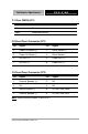
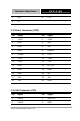
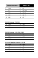
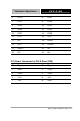
2.5 List of Connectors
The board has a number of connectors that allow you to configure
your system to suit your application. The table below shows the
function of each board's connectors:
Label Function
ATX2 ATX Power Connector
ATX1 ATX Power_12V Connector
SATA1 & 3 Serial ATA Connector
CN1 VGA Display PIN HEADER
IDE1 IDE Connector
USB1 USB Connector
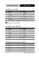
CN4、5
USB PIN HEADER
COM2 RS-232 Serial Port PIN HEADER
COM1 RS-232 Serial Port Connector
DIMM1~2 DIMM Slot
FAN1~3 Fan Connector
CPUFAN1 Fan Connector
LAN1~8 RJ-45 PHONEJACK Connector
CN7 PS2 Keyboard/Mouse Connector
PWR1 SATA POWER Connector
CFD1 Compact Flash Slot
MPCI1 Mini PCI Slot
LCMA1 LCM & Key Pad Control PIN HEADER
CN8 Power Connector for PCI-X Riser
Note: DIMM height limitation is 31mm; DOM height limitation is 29mm.