Industrial Motherboard IMBA-H61A
E7929 First Edition February 2013 Copyright Notice This document is copyrighted, 2013. All rights are reserved. The original manufacturer reserves the right to make improvements to the products described in this manual at any time without notice. No part of this manual may be reproduced, copied, translated, or transmitted in any form or by any means without the prior written permission of the original manufacturer. Information provided in this manual is intended to be accurate and reliable.
Contents Chapter 1 Product overview 1.1 Package contents.......................................................................... 1-1 1.3 Specifications................................................................................ 1-2 1.2 Features......................................................................................... 1-1 Chapter 2 Motherboard information 2.1 Before you proceed...................................................................... 2-1 2.3 Screw size..............
Contents 3.4 Advanced menu............................................................................ 3-6 3.4.1 CPU Configuration........................................................... 3-7 3.4.4 SATA Configuration.......................................................... 3-8 3.4.3 3.4.5 3.4.6 3.4.7 PCH Configuration........................................................... 3-8 System Agent Configuration............................................ 3-9 USB Configuration............................
Chapter 1 Product overview 1.1 Package contents Check your industrial motherboard package for the following items. 1 x Industrial Motherboard 2 x Serial ATA 3.0Gb/s cables 1 x I/O Shield 1 x Support DVD (Drivers and manual) 1 x COM Port cable If any of the above items is damaged or missing, contact your distributor or sales representative immediately. 1.
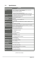
1.3 Specifications Form factor CPU SYSTEM ATX Form Factor LGA1155 socket for Intel® 3rd/2nd Generation Core™ i7 / Core™ i5 / Core™ i3 / Pentium® / Celeron® processors Supports Intel® 22nm / 32nm CPU Supports Intel® Turbo Boost Technology 2.0 Memory Chipset I/O Chipset Ethernet BIOS Manageability OS H/W Status Monitor Expansion slot • The Intel® Turbo Boost Technology 2.0 support depends on the CPU types. 2 x DIMM (8GB per DIMM), max.
DISPLAY Chipset Resolution Intel® Graphics Media Accelerator Output interface 1 x VGA port Up to 1920x1200@60Hz for VGA Storage Serial port 1 x DVI port I/O 4 x SATA 3.0Gb/s ports 1 x RS232 DB-9 connector (COM1) 1 x RS232/422/485 on rear I/O (COM2) USB DIO LPT TPM RTC Keyboard/Mouse Audio Ethernet Up to 1920x1200@60Hz for DVI 4 x RS232 box header (COM3~COM6) 9 x USB2.
1-4 IMBA-H61A
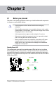
Chapter 2 Motherboard information 2.1 Before you proceed Take note of the following precautions before you install motherboard components or change any motherboard settings. • Unplug the power cord from the wall socket before touching any component. • Before handling components, use a grounded wrist strap or touch a safely grounded object or a metal object, such as the power supply case, to avoid damaging them due to static electricity.
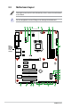
2.2 Motherboard layout Place eight screws into the holes indicated by circles to secure the motherboard to the chassis. Do not overtighten the screws! Doing so can damage the motherboard. 1 2 3 4 5 3 6 4 24.4cm(9.6in) EATX_PWR2 RTL 8111F COM4 VGA1 LAN2_USB34 1 EATX_PWR1 RTL 8111F CPU_FAN1 AUDIO COM6 LAN1_USB12 30.
Connectors/Jumpers/Slots 1. Serial port connectors (10-1 pin COMBH2, COM3~6) 2 COM2_V1 Ring/+5V/+12V selection (6-pin) 3. CPU and chassis fan connectors (4-pin CPU_FAN, 4-pin CHA_FAN) 4. ATX power connectors (24-pin EATXPWR, 4-pin EATX12V) 5. Intel® LGA1155 CPU socket 6. DDR3 DIMM slots Page 21 13 17 16 6 11 7. 8. 9. 10. 11 12. 13. 14. 15. 16. 17.
2.3 2.3.
2.3.
2.4 Central Processing Unit (CPU) The motherboard comes with a surface mount LGA1155 socket designed for the Intel® 3rd/2nd Generation Core™ i7 / Core™ i5 / Core™ i3 / Pentium® / Celeron® processors. IMBA-H61A CPU socket LGA1155 Unplug all power cables before installing the CPU. 2-6 • Upon purchase of the motherboard, ensure that the PnP cap is on the socket and the socket contacts are not bent.
2.4.1 Installing the CPU The LGA1156 CPU is incompatible with the LGA1155 socket. DO NOT install a LGA1156 CPU on the LGA1155 socket.
4 C A B 5 2-8 IMBA-H61A
2.4.2 CPU heatsink and fan assembly installation Apply the Thermal Interface Material to the CPU heatsink and CPU before you install the heatsink and fan if necessary.
To uninstall the CPU heatsink and fan assembly 1 2 A B B A 2-10 IMBA-H61A
2.
2.6 1. Jumpers Clear RTC RAM (CLRTC) This jumper allows you to clear the Real Time Clock (RTC) RAM in CMOS. You can clear the CMOS memory of date, time, and system setup parameters by erasing the CMOS RTC RAM data. The onboard button cell battery powers the RAM data in CMOS, which include system setup information such as system passwords. CLRTC1 3 2 2 Normal (Default) Clear RTC1 1 IMBM-H61A Clear RTC RAM To erase the RTC RAM: 1. Turn OFF the computer and unplug the power cord. 2.
2. COM2_V Ring/+5V/+12V selection (6-pin) 1 2 3 +12V 4 +5V 5 6 Ring (Default) IMBM-H61A COM2_V1 Ring/+5V/+12V Selection 3.
2.7 Connectors 2.7.1 1. 2. 3. 4. Rear panel connectors 1 2 3 10 2 9 4 8 5 6 8 7 PS/2 Mouse port (green). This port is for a PS/2 mouse. Serial ports. These ports connect a modem, or other devices that conform with serial specification. Video Graphics Adapter (VGA) port. This 15-pin port is for a VGA monitor or other VGA-compatible devices. LAN (RJ-45) ports. These ports allow Gigabit connection to a Local Area Network (LAN) through a network hub.
5. 6. 7. Line In port (light blue). This port connects to the tape, CD, DVD player, or other audio sources. Line Out port (lime). This port connects to a headphone or a speaker. In the 4, 6, and 8-channel configurations, the function of this port becomes Front Speaker Out. Microphone port (pink). This port connects to a microphone. To configure an 8-channel audio output: Use a chassis with HD audio module in the front panel to support an 8-channel audio output.
2.7.2 1. Internal connectors ATX power connectors (24-pin EATXPWR, 4-pin EATX12V) These connectors are for ATX power supply plugs. The power supply plugs are designed to fit these connectors in only one orientation. Find the proper orientation and push down firmly until the connectors completely fit.
2. CPU and chassis fan connectors (4-pin CPU_FAN, 4-pin CHA_FAN1/2) Connect the fan cables to the fan connectors on the motherboard, ensuring that the black wire of each cable matches the ground pin of the connector. CHA FAN PWM CHA FAN SENSE CHA FAN VCC GND CHA_FAN1 CHA_FAN2 CHA FAN PWM CHA FAN SENSE CHA FAN VCC GND CPU FAN PWM CPU FAN SENSE CPU FAN VCC GND CPU_FAN IMBA-H61A Fan connectors Do not forget to connect the fan cables to the fan connectors.
4. System panel connector (10-1 pin F_PANEL) This connector supports several chassis-mounted functions. F_PANEL1 PLED+ PLEDPWR GND PWR LED PWR BTN HD_LED+ HD_LEDGround HWRST# (NC) PIN 1 +HD_LED RESET IMBA-H61A System panel connector • • • • 2-18 System power LED (2-pin PLED) This 2-pin connector is for the system power LED. Connect the chassis power LED cable to this connector. The system power LED lights up when you turn on the system power, and blinks when the system is in sleep mode.
Intel® H61 Serial ATA 3.0Gb/s connectors (7-pin SATA3G_1~3) SATA3G_1 SATA3G_2 SATA3G_3 SATA3G_4 GND RSATA_RXP2 RSATA_RXN2 GND RSATA_TXN2 RSATA_TXP2 GND GND RSATA_RXP3 RSATA_RXN3 GND RSATA_TXN3 RSATA_TXP3 GND GND RSATA_RXP4 RSATA_RXN4 GND RSATA_TXN4 RSATA_TXP4 GND These connectors connect to Serial ATA 3.0 Gb/s hard disk drives and optical drives via Serial ATA 3.0 Gb/s signal cables. GND RSATA_RXP1 RSATA_RXN1 GND RSATA_TXN1 RSATA_TXP1 GND 5. IMBA-H61A Intel® SATA 3.0Gb/s connectors 6.
USB 2.0 connectors (10-1 pin USB89, USB45; 5-pin USB10) These connectors are for USB 2.0 ports. Connect the USB module cable to any of these connectors, then install the module to a slot opening at the back of the system chassis. These USB connectors comply with USB 2.0 specification that supports up to 480 Mbps connection speed. +5V USBDUSBD+ GND GND GND PIN 1 PIN 1 +5V USB8USB8+ GND PIN 1 USB45 +5V USB5USB5+ GND (NC) USB89 +5V USB9USB9+ GND (NC) USB10 +5V USB4USB4+ GND 7. IMBA-H61A Front USB 2.
9. Serial port connectors (10-1 pin COM1/2, COM3~6) These connectors are for serial (COM) ports. Connect the serial port module cable to this connector, then install the module to a slot opening at the back of the system chassis.
11. Direct connector (2-pin DRCT) This connector is for the chassis-mounted button that supports the DirectKey function. Connect the button cable that supports DirectKey from the chassis to this connector on the motherboard.
Chapter 3 BIOS setup 3.1 BIOS setup program Use the BIOS Setup program to update the BIOS or configure its parameters. The BIOS screens include navigation keys and brief online help to guide you in using the BIOS Setup program. Entering BIOS Setup at startup To enter BIOS Setup at startup: • Press during the Power-On Self Test (POST). If you do not press , POST continues with its routines.
3.2 BIOS menu screen Back button Menu items Menu bar Pop-up window Configuration fields General help Navigation keys Menu bar The menu bar on top of the screen has the following main items: Main Advanced Boot Tool Exit 3-2 For changing the basic system configuration. For changing the advanced system settings. For changing the system boot configuration. For configuring options for special functions. For selecting the exit options and loading default settings.
Menu items The highlighted item on the menu bar displays the specific items for that menu. For example, selecting Main shows the Main menu items. The other items (Ai Tweaker, Advanced, Monitor, Boot, Tool, and Exit) on the menu bar have their respective menu items. Back button This button appears when entering a submenu. Press or use the USB mouse to click this button to return to the previous menu screen.
3.3 Main menu The Main menu screen appears when you enter the Advanced Mode of the BIOS Setup program. The Main menu provides you an overview of the basic system information, and allows you to set the system date, time, language, and security settings. 3.3.1 System Language [English] 3.3.2 System Date [Day xx/xx/xxxx] 3.3.3 System Time [xx:xx:xx] 3.3.4 Security Allows you to choose the BIOS language version from the options. Configuration options: [English] Allows you to set the system date.
Administrator Password If you have set an administrator password, we recommend that you enter the administrator password for accessing the system. Otherwise, you might be able to see or change only selected fields in the BIOS setup program. To set an administrator password: 1. Select the Administrator Password item and press . 2. From the Create New Password box, key in a password, then press . 3. Confirm the password when prompted. To change an administrator password: 1. 2.
To clear the user password, follow the same steps as in changing a user password, but press when prompted to create/confirm the password. After you clear the password, the User Password item on top of the screen shows Not Installed. 3.4 Advanced menu The Advanced menu items allow you to change the settings for the CPU and other system devices. Be cautious when changing the settings of the Advanced menu items. Incorrect field values can cause the system to malfunction. 3.4.
3.4.2 CPU Configuration The items in this menu show the CPU-related information that the BIOS automatically detects. The items shown in submenu may be different due to the CPU you installed. Intel® Adaptive Thermal Monitor [Enabled] [Enabled] Enables the overheated CPU to throttle its clock speed to cool down. [Disabled] Disables the CPU thermal monitor function. Hyper-threading [Enabled] This item will only appear if an Intel® processor supporting Hyper-Threading is installed on the motherboard.
Intel Virtualization Technology [Disabled] [Enabled] Allows a hardware platform to run multiple operating systems separately and simultaneously, enabling one system to virtually function as several systems. [Disabled] Disables this function. Hardware Prefetcher [Enabled] [Disabled] Disables this function. [Enabled] Allows you to turn on /off the Mid Level Cache (L2) streamer prefetcher. Adjacent Cache Line Prefetch [Enabled] [Disabled] Disables this function.
S.M.A.R.T. Status Check [Enabled] S.M.A.R.T. (Self-Monitoring, Analysis and Reporting Technology) is a monitor system. When read/write of your hard disk errors occur, this feature allows the hard disk to report warning messages during the POST. Configuration options: [Enabled] [Disabled] Hot Plug [Disabled] This item only appears when you set the SATA Mode Selection item to [AHCI] and allows you to enable or disable the hot-plug support for each SATA port. Configuration options: [Enabled] [Disabled] 3.4.
3.4.6 USB Configuration The items in this menu allow you to change the USB-related features. The USB Devices item shows the auto-detected values. If no USB device is detected, the item shows None. Legacy USB Support [Enabled] [Enabled] Enables the support for USB devices on legacy operating systems (OS). [Disabled] The USB devices can be used only for the BIOS setup program. [Auto] Allows the system to detect the presence of USB devices at startup.
3.4.8 Onboard Devices Configuration HD Audio Controller [Enabled] [Enabled] [Disabled] Enables the High Definition Audio Controller. Disables the controller. Realtek LAN1 Controller [Enabled] [Enabled] [Disabled] Enables the Realtek LAN controller 1. Disables the controller. Realtek LAN1 PXE OPROM [Disabled] This item appears only when you set the Realtek LAN1 Controller item to [Enabled] and allows you to enable or disable the PXE OptionRom of the Realtek LAN controller 1.
Power On By PCIE/PCI [Disabled] [Disabled] [Enabled] Disables the PCIE/PCI devices to generate a wake event. Enables the PCIE/PCI devices to generate a wake event. Power On By Ring [Disabled] [Disabled] [Enabled] Disables Ring to generate a wake event. Enables Ring to generate a wake event. Power On By RTC [Disabled] [Disabled] Disables RTC to generate a wake event. [Enabled] When set to [Enabled], the items RTC Alarm Date (Days) and Hour/Minute/Second will become user-configurable with set values.
3.5 Monitor menu The Monitor menu displays the system temperature/power status, and allows you to change the fan settings. 3.5.1 CPU Temperature / MB Temperature [xxxºC/xxxºF] The onboard hardware monitor automatically detects and displays the CPU and motherboard temperatures. Select Ignore if you do not wish to display the detected temperatures. 3.5.
3.5.3 [Disabled] [Enabled] CPU Q-Fan Control [Enabled] Disables the CPU Q-Fan control feature. Enables the CPU Q-Fan control feature. CPU Fan Profile [Standard] This item appears only when you enable the CPU Q-Fan Control feature and allows you to set the appropriate performance level of the CPU fan. [Standard] Sets to [Standard] to make the CPU fan automatically adjust depending on the CPU temperature. [Silent] Sets to [Silent] to minimize the fan speed for quiet CPU fan operation.
3.6 Boot menu The Boot menu items allow you to change the system boot options. 3.6.1 [Enabled] [Disabled] Full Screen Logo [Enabled] Enables the full screen logo display feature. Disables the full screen logo display feature. Post Report [5 sec] This item appears only when the Full Screen Logo item is set to [Disabled] and allows you to set the waiting time for the system to display the post report.
3.6.4 Wait for ‘F1’ If Error [Disabled] 3.6.5 Option ROM Messages [Force BIOS] When this item is set to [Enabled], the system waits for the F1 key to be pressed when error occurs. Configuration options: [Disabled] [Enabled] [Force BIOS] The third-party ROM messages will be forced to display during the boot sequence. [Keep Current] The third-party ROM messages will be displayed only if the thirdparty manufacturer had set the add-on device to do so. 3.6.
3.6.7 Boot Option Priorities These items specify the boot device priority sequence from the available devices. The number of device items that appears on the screen depends on the number of devices installed in the system. • To select boot device during system startup, press after the first screen appears. • To access Windows OS in Safe Mode, press after POST. 3.6.8 Boot Override 3.7 Tools menu These items displays the available devices.
3.8 Exit menu The Exit menu items allow you to load the optimal default values for the BIOS items, and save or discard your changes to the BIOS items. You can access the EZ Mode from the Exit menu. Load Optimized Defaults This option allows you to load the default values for each of the parameters on the Setup menus. When you select this option or if you press , a confirmation window appears. Select Yes to load the default values.
Appendix Notices Federal Communications Commission Statement This device complies with Part 15 of the FCC Rules. Operation is subject to the following two conditions: • This device may not cause harmful interference. • This device must accept any interference received including interference that may cause undesired operation. This equipment has been tested and found to comply with the limits for a Class A digital device, pursuant to Part 15 of the FCC Rules.
DO NOT throw the motherboard in municipal waste. This product has been designed to enable proper reuse of parts and recycling. This symbol of the crossed out wheeled bin indicates that the product (electrical and electronic equipment) should not be placed in municipal waste. Check local regulations for disposal of electronic products. DO NOT throw the mercury-containing button cell battery in municipal waste.