Industrial Motherboard IMBA-Q87A
E8548 First Edition August 2013 Copyright Notice This document is copyrighted, 2013. All rights are reserved. The original manufacturer reserves the right to make improvements to the products described in this manual at any time without notice. No part of this manual may be reproduced, copied, translated, or transmitted in any form or by any means without the prior written permission of the original manufacturer. Information provided in this manual is intended to be accurate and reliable.
Contents Chapter 1 Product overview 1.1 Package contents.......................................................................... 1-1 1.3 Specifications................................................................................ 1-2 1.2 Features......................................................................................... 1-1 Chapter 2 Motherboard information 2-1 2.1 Before you proceed...................................................................... 2-1 2.3 Screw size....
3.3.6 SATA Configuration.......................................................... 3-5 3.3.8 AMT Configuration........................................................... 3-6 3.3.7 3.3.9 3.3.10 3.3.11 3.4 3.5 3.6 3.7 3.3.12 PCH-FW Configuration.................................................... 3-6 USB Configuration........................................................... 3-6 F81216 Second Super IO Configuration.......................... 3-7 NCT6791D Super IO Configuration.......................
Chapter 1 Product overview 1.1 Package contents Check your industrial motherboard package for the following items. 1 x Industrial Motherboard 1 x SATA 6G cable 1 x I/O Shield 1 x COM port cable 1 x Support CD If any of the above items is damaged or missing, contact your distributor or sales representative immediately. 1.
1.3 Specifications Form factor CPU SYSTEM ATX LGA1150 socket for Intel® 4th Generation Core™ i7 / Core™ i5 / Core™ i3 processors Supports Intel® 22nm CPU Supports Intel® Turbo Boost Technology 2.0* Memory Chipset I/O Chipset Ethernet BIOS Wake on LAN Watchdog Timer TPM H/W Status Monitor Smart Fan Control Power State Expansion slot Battery *Intel® Turbo Boost Technology 2.0 support depends on the CPU types. 4 x DIMM (8GB per DIMM), max.
Chipset Resolution DISPLAY Intel® Graphics Media Accelerator Up to 1920x1200@60Hz for VGA Up to 1920x1200@60Hz for DVI Up to 4096x2610@24Hz for HDMI Output interface Up to 2560x1440@60Hz for Display Port SKU1 (VGA / DVI / HDMI / DP) VGA+DVI, VGA+HDMI, VGA+DP, DVI+HDMI, DVI+DP, HDMI+DP, VGA+DVI+HDMI, VGA+DVI+DP, DVI+HDMI+DP, HDMI+DP+VGA SKU2 (VGA / DVI / 2xHDMI) VGA+DVI, VGA+HDMI1, VGA+HDMI2, DVI+HDMI1, DVI+HDMI2, HDMI1+HDMI2, VGA+HDMI1+HDMI2, VGA+HDMI1+DVI I/O Storage 6 x SATA 6.
1-4 IMBA-Q87A
Chapter 2 Motherboard information 2.1 Before you proceed Take note of the following precautions before you install motherboard components or change any motherboard settings. CAUTION! • Unplug the power cord from the wall socket before touching any component. • Before handling components, use a grounded wrist strap or touch a safely grounded object or a metal object, such as the power supply case, to avoid damaging them due to static electricity.
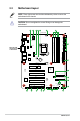
2.2 Motherboard layout NOTE: Place eight screws into the holes indicated by circles to secure the motherboard to the chassis. CAUTION! Do not overtighten the screws! Doing so can damage the motherboard. 1 2 3 4 5 4 6 24.4cm(9.6in) CPU_FAN1 COM3 KBMS1 HDMI1 VGA COM4 COM5 COM6 CHA_FAN1 Intel® PHY EATX_PWR1 LAN2_USB3_34 I210AT BATTERY AUDIO1 7 30.
Connectors/Jumpers/Slots 1. COM1 VSET connector (COM1_V1) 2. ATX power connectors (24-pin EATXPWR1, 8-pin EATX_PWR2) 3. VGA connector (16-pin VGA) 4. CPU and system fan connectors (4-pin CPU_FAN1, 4-pin CHA_FAN1~2) 5. Intel® LGA1150 CPU socket Page 2-14 2-19 2-23 2-20 2-6 Intel® ME Jumper (3-pin DIS_ME) Serial ATA 6.0Gb/s connectors (7-pin SATA6G_1~6) Standby Power LED (SB_PWR1~2) Clear RTC RAM (CLRTC) System panel connector (10-1 pin F_PANEL1) USB 2.
2.3 2.3.
2.3.
2.4 Central Processing Unit (CPU) The motherboard comes with a surface mount LGA1150 socket designed for the Intel® 4th Generation Core™ i7 / Core™ i5 / Core™ i3 / Pentium® / Celeron® processors. IMBA-Q87A CPU socket LGA1150 IMPORTANT: Unplug all power cables before installing the CPU. CAUTION! 2-6 • Upon purchase of the motherboard, ensure that the PnP cap is on the socket and the socket contacts are not bent.
2.4.1 Installing the CPU CAUTION! Ensure that you install the correct CPU designed for LGA 1150 only. DO NOT install a CPU designed for LGA1155 and LGA1156 sockets on the LGA1150 socket.
4 C A B 5 2-8 IMBA-Q87A
2.4.2 CPU heatsink and fan assembly installation CAUTION! Apply the Thermal Interface Material to the CPU heatsink and CPU before you install the heatsink and fan if necessary.
To uninstall the CPU heatsink and fan assembly 1 2 A B B A 2-10 IMBA-Q87A
2.5 System memory This motherboard comes with four Double Data Rate 3 (DDR3) Dual Inline Memory Module (DIMM) sockets. A DDR3 module has the same physical dimensions as a DDR2 DIMM but is notched differently to prevent installation on a DDR2 DIMM socket. DDR3 modules are developed for better performance with less power consumption.
2.5.
2.6 1. Jumpers Clear RTC RAM (CLRTC) This jumper allows you to clear the Real Time Clock (RTC) RAM in CMOS. You can clear the CMOS memory of system setup parameters by erasing the CMOS RTC RAM data. The onboard button cell battery powers the RAM data in CMOS, which include system setup information such as system passwords. 1 2 CLRTC Normal (Default) 2 3 Clear RTC1 IMBA-Q87A Clear RTC RAM To erase the RTC RAM: 1. Turn OFF the computer and unplug the power cord. 2.
2. Intel® ME Jumper (3-pin DIS_ME) This jumper allows you to force the Intel® Management Engine (ME) to boot to recovery mode when ME becomes corrupted. DIS_ME 1 2 2 ME Enable (Default) 3 ME Disable IMBA-Q87A Intel® ME jumper 3.
2.7 1. Onboard LEDs Standby Power LED The motherboard comes with two standby power LEDs that light up to indicate that the system is ON, in sleep mode or in soft-off mode. This is a reminder that you should shut down the system and unplug the power cable before removing or plugging in any motherboard component. The illustration below shows the location of the onboard LEDs.
2.8 Connectors 2.8.1 Rear panel connectors 1 11 1. 2. 2-16 10 9 2 3 4 5 8 7 6 PS/2 keyboard/mouse port (purple/green). This port is for a PS/2 keyboard or mouse. Serial port (COM port). This port connects to a modem, or other device that conforms with serial specification.
3. LAN1~2 (RJ-45) port. These ports allow Gigabit connection to a Local Area Network (LAN) through a network hub. Refer to the table below for the LAN1 port LED indications. LAN1 port LED indications ACT/LINK LED Status Description OFF No link 4. 5. 6. ORANGE Linked BLINKING Data activity SPEED LED Status Description OFF 10 Mbps connection ORANGE 100 Mbps connection GREEN 1 Gbps connection Activity Link LED Speed LED LAN port Line In port (light blue).
Audio 2.1, 4.1, or 5.1-channel configuration Headset 2.1-channel Port Light Blue (Rear panel) Line In Lime (Rear panel) Line Out Pink (Rear panel) Lime (Front panel) Mic In - 7. 4.1-channel Rear Speaker Out Front Speaker Out Mic In - 5.1-channel Rear Speaker Out Front Speaker Out Bass/Center - USB1~4 3.0 ports. These 9-pin Universal Serial Bus (USB) ports connect to USB 3.0/2.0 devices. NOTES: 8. 9. • DO NOT connect a keyboard / mouse to any USB 3.
2.8.2 1. Internal connectors ATX power connectors (24-pin EATX_PWR1, 8-pin EATX_PWR2) These connectors are for ATX power supply plugs. The power supply plugs are designed to fit these connectors in only one orientation. Find the proper orientation and push down firmly until the connectors completely fit.
3. CPU and chassis fan connectors (4-pin CPU_FAN1, 4-pin CHA_FAN1~2) Connect the fan cables to the fan connectors on the motherboard, ensuring that the black wire of each cable matches the ground pin of the connector. CHA FAN PWM CHA FAN SENSE CHA FAN VCC GND CHA_FAN1 CHA FAN PWM CHA FAN SENSE CHA FAN VCC GND CPU FAN PWM CPU FAN SENSE CPU FAN VCC GND CPU_FAN1 CHA_FAN2 IMBA-Q87A Fan connectors CAUTION: Do not forget to connect the fan cables to the fan connectors.
5. System panel connector (10-1 pin F_PANEL1) This connector supports several chassis-mounted functions. F_PANEL1 PLED+ PLEDPWR GND PWR LED PWR BTN HD_LED+ HD_LEDGround HWRST# (NC) PIN 1 +HD_LED RESET IMBA-Q87A System panel connector • • • • System power LED (2-pin PWR_LED) This 2-pin connector is for the system power LED. Connect the chassis power LED cable to this connector. The system power LED lights up when you turn on the system power, and blinks when the system is in sleep mode.
Serial ATA 6.0Gb/s connector (7-pin SATA6G_1~6) ThIS connector connects to Serial ATA 6.0 Gb/s hard disk drives via Serial ATA 6.0 Gb/s signal cables.
USB 2.0 connector (10-1 pin USB1112, USB56, USB78, USB910) These connector are for USB 2.0 ports. Connect the USB module cable to the connectors. These USB connectors comply with USB 2.0 specifications that supports up to 480 Mbps connection speed. +5V USB9USB9+ GND (NC) +5V USB11USB11+ GND (NC) USB1112 PIN 1 +5V USB10USB10+ GND PIN 1 +5V USB12USB12+ GND PIN 1 +5V USB6USB6+ GND PIN 1 USB910 +5V USB7USB7+ GND (NC) USB78 +5V USB5USB5+ GND (NC) USB56 +5V USB8USB8+ GND 8.
10. Serial port connectors (10-1 pin COM2~6) These connectors are for serial (COM) ports. Connect the serial port module cables to these connectors, then install the module to a slot opening at the back of the system chassis.
Chapter 3 BIOS setup 3.1 BIOS setup program Use the BIOS Setup program to update the BIOS or configure its parameters. The BIOS screens include navigation keys and brief online help to guide you in using the BIOS Setup program. Entering BIOS Setup at startup To enter BIOS Setup at startup: Press during the Power-On Self Test (POST). If you do not press , POST continues with its routine.
3.1.1 BIOS menu screen 3.1.2 Menu bar The menu bar on top of the screen has the following main items: Main Advanced Chipset For changing the basic system configuration. For changing the advanced system settings. For viewing and changing chipset settings. Boot For changing the system boot configuration. Security For setting up BIOS security settings. Save & Exit For selecting the exit options and loading default settings.
3.3 Advanced menu The Advanced menu items allow you to change the settings for the CPU and other system devices. Be cautious when changing the settings of the Advanced menu items. Incorrect field values can cause the system to malfunction. 3.3.1 S5 RTC Wake Settings Wake System with Fixed Time [Disabled] Enable or disable system wake on at an alarm event. When enabled, the system will wake up at the specified hr::min::sec.
3.3.2 Dynamic Digital IO The items listed in this screen configure Digital IO settings. DI00~DI03 Direction [Input] Configuration options: [Input] [Output] DI04~DI07 Direction [Output] Configuration options: [Input] [Output] Output Level [Hi] Configuration options: [Hi] [Low] 3.3.3 ACPI Settings ACPI Sleep State [S3 only (Suspend to...)] This item selects the ACPI sleep state the system will enter when the system is in Suspend mode.
3.3.5 CPU Configuration The items in this menu show CPU-related information the BIOS automatically detects. The items shown in the submenu may be different depending on the type of CPU installed. Hyper-threading [Enabled] The Intel Hyper-Threading Technology allows a hyper-threading processor to appear as two logical processors to the operating system, allowing the operating system to schedule two threads or processes simultaneously. [Enabled] Two threads per activated core are enabled.
3.3.7 PCH-FW Configuration This screen displays ME Firmware Mode, Type, SKU and version. 3.3.8 AMT Configuration The items in this menu allow you to change the Intel® Active Management Technology (AMT) feature. Intel® AMT [Enabled] Allow you to enable or disable the Intel® Active Management Technology (AMT) in the BIOS extension. Configuration options: [Enabled] [Disabled] • iAMT H/W is always enabled. This option just controls the BIOS extension execution.
3.3.10 F81216 Second Super IO Configuration The items in this menu allow you to configure Serial Port settings. Serial Port 3~6 Configuration Serial Port [Enabled] Allows you to enable or disable the serial port (COM). Configuration options: [Enabled] [Disabled] Change Settings [Auto] Allows you to select the Serial Port base address. Configuration options: [IO=2C0h; IRQ=5] [IO=2C8h; IRQ=5] [IO=2B0h; IRQ=5] [IO=2B8h; IRQ=5] The following item is only supported by Serial Port 3. 3.3.
Parallel Port Configuration The sub-items in this menu allow you to set the parallel port configuration. Parallel Port [Enabled] Allows you to enable or disable the parallel port (LPT/LPTE). Configuration options: [Enabled] [Disabled] The following items appear only when you set the Parallel Port Configuration item to [Enabled]. Change Settings [Auto] Allows you to select an optimal setting for Super I/O devices.
Fan Control Mode [Thermal Cruise Mode] Configuration options: [Manual Mode] [Thermal Cruise Mode] [Speed Cruise Mode] [Smart Fan IV Mode] The following items appear only when you set Fan Control Mode to [Thermal Cruise Mode].
The following item appears only when you set Fan Control Mode to [Manual Mode]. PWM/DC Voltage Output [255] Sets the voltage allocated for Fan Control. Input value range: [0~255] The following items appear only when you set Fan Control Mode to [Speed Cruise Mode]. Target Speed [0] Input value range: [0~4096] Speed Tolerance [2] Input value range: [0~64] Fan Out Step Up Time [10] Determines the amount of time Fan Out takes to increase its value by one step.
Critical Temp Tolerance [0] Input value range: [0~7] Fan Count Step Up [5] Input value range: [0~15] Fan Count Step Down [5] Input value range: [0~15] Fan Out Step Up Time [10] Determines the amount of time Fan Out takes to increase its value by one step. Input value range: [0~255] Fan Out Step Down Time [10] Determines the amount of time Fan Out takes to decrease its value by one step in intervals of 0.1 seconds.
3.4 Chipset menu The Chipset menu items allow you to change the settings for the chipset. 3.4.1 System Agent (SA) Configuration VT-d [Enabled] Allows you to enable virtualization technology function on memory control hub. [Enabled] Enables the function. [Disabled] Disables this function. The VT-d feature is available only for specific types of CPU. PCIEx16_1 Link Speed [Auto] Allows you to configure the PCIEx16 speed.
Memory Information This screen displays detailed memory information including currently available physical memory, total memory and installed DIMMs. 3.4.2 PCH-IO Configuration Power Mode [ATX Type] This item selects Power Supply Mode. Configuration options: [ATX Type] [AT Type] Resume on Ring [Enabled] This item disables/enables resuming system on ring.
3.5 Boot menu The Boot menu items allow you to change the system boot options. 3.5.1 Boot Configuration Quick Boot [Enabled] This item enables/disables Quiet Boot. Configuration options: [Auto] [Gen1] [Gen2] [Gen3] Launch I217LM PXE OpROM [Disabled] This item enables/disables Legacy Boot Option for I217LM. Configuration options: [Disabled] [Enabled] Launch WGI210AT PXE OpROM [Disabled] This item enables/disables Legacy Boot Option for WGI210AT. Configuration options: [Disabled] [Enabled] 3.5.
3.6 Security menu The Security menu items allow you to change the system security settings. 3.6.1 Administrator Password If you have set an administrator password, we recommend that you enter the administrator password for accessing the system. Otherwise, you might be able to see or change only selected fields in the BIOS setup program. To set an administrator password: 1. Select the Administrator Password item and press . 2.
To change a user password: 1. 2. Select the User Password item and press . From the Enter Current Password box, key in the current password, then press . 3. From the Create New Password box, key in a new password, then press . 4. Confirm the password when prompted. To clear the user password, follow the same steps as in changing a user password, but press when prompted to create/confirm the password.
3.7 Save & Exit menu Save Changes & Reset Once you are finished making your selections, choose this option from the Exit menu to ensure the values you selected are saved. When you select this option or if you press , a confirmation window appears. Select Yes to save changes and exit. Discard Changes & Reset This option allows you to exit the Setup program without saving your changes. When you select this option or if you press , a confirmation window appears.
3-18 IMBA-Q87A
Appendix Notices Federal Communications Commission Statement This device complies with Part 15 of the FCC Rules. Operation is subject to the following two conditions: • This device may not cause harmful interference. • This device must accept any interference received including interference that may cause undesired operation. This equipment has been tested and found to comply with the limits for a Class A digital device, pursuant to Part 15 of the FCC Rules.
電子信息產品污染控制標示:圖中之數字為產品之環保使用期限。僅指電子 信息產品中含有的有毒有害物質或元素不致發生外洩或突變從而對環境造成 污染或對人身、財產造成嚴重損害的期限。 有毒有害物質或元素的名稱及含量說明標示: 有害物質或元素 部件名稱 鉛 (Pb) 汞 (Hg) 鎘 (Cd) 六 價 (Cr(VI)) 印刷電路板及其 電子組件 × ○ ○ 外部信號連接頭 及線材 × ○ ○ 鉻 多 溴 聯 苯 (PBB) 多溴二苯醚 (PBDE) ○ ○ ○ ○ ○ ○ ○: 表示該有毒有害物質在該部件所有均質材料中的含量均在 SJ/T 113632006 標准規定的限量要求以下。 ×: 表示該有毒有害物質至少在該部件的某一均質材料中的含量超出 SJ/T 11363-2006 標准規定的限量要求,然該部件仍符合歐盟指令 2002/95/ EC 的規范。 備註:此產品所標示之環保使用期限,係指在一般正常使用狀況下。 A-2 IMBA-Q87A