PC/104 CPU Module PFM-LNP PFM-LNP ® Intel Atom™ N450 Processor ® Intel N450+ICH8M 18-bit Single Channel LVDS LCD 1 SATA 2, 1 CompactFlash™ 4 COM, 4 USB PFM-LNP Manual Rev.A 2nd Ed.
PC/104 CPU Module PFM-LNP Copyright Notice This document is copyrighted, 2014. All rights are reserved. The original manufacturer reserves the right to make improvements to the products described in this manual at any time without notice. No part of this manual may be reproduced, copied, translated, or transmitted in any form or by any means without the prior written permission of the original manufacturer. Information provided in this manual is intended to be accurate and reliable.
PC/104 CPU Module PFM-LNP Acknowledgments All other products’ name or trademarks are properties of their respective owners. Award is a trademark of Award Software International, Inc. CompactFlash™ is a trademark of the Compact Flash Association. Microsoft Windows is a registered trademark of Microsoft Corp. Intel , Atom™ are trademarks of Intel Corporation. ITE is a trademark of Integrated Technology Express, Inc.
PC/104 CPU Module PFM-LNP Packing List Before you begin installing your card, please make sure that the following materials have been shipped: PFM-LNP CD-ROM for manual (in PDF format) and drivers Jumper cap Note: If any of these items should be missing or damaged, please contact your distributor or sales representative immediately.
PC/104 CPU Module PFM-LNP Contents Chapter 1 General Information 1.1 Introduction ................................................................ 1-2 1.2 Features .................................................................... 1-3 1.3 Specifications ............................................................ 1-4 Chapter 2 Quick Installation Guide 2.1 Safety Precautions .................................................... 2-2 2.2 Location of Connectors and Jumpers ....................... 2-3 2.
PC/104 CPU Module PFM-LNP 2.18 Front Panel Connector (CN8) ................................. 2-10 2.19 LAN LED Connector (CN9) ..................................... 2-11 2.20 RS-232 Serial Port Connector (COM1) ................... 2-11 2.21 RS-232/422/485 Serial Port Connector (COM2) ..... 2-12 2.22 RS-232 Serial Port Connector (COM3) ................... 2-12 2.23 RS-232 Serial Port Connector (COM4) ................... 2-13 2.24 1000Base-TX Ethernet Connector (LAN1) ............. 2-13 2.
PC/104 CPU Module PFM-LNP B.3 IRQ Mapping Chart ................................................B-3 B.4 DMA Channel Assignments ...................................B-3 Appendix C Mating Connector C.1 List of Mating Connectors and Cables..................
PC/104 CPU Module PFM-LNP Chapter 1 General Information Chapter 1 General Information 1- 1
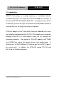
PC/104 CPU Module PFM-LNP 1.1 Introduction AAEON Technology, a leading company in embedded boards manufacturing with a full range of PC/104 CPU Modules, launches a brand new PC/104 CPU Module-PFM-LNP. Its compact size and rich functionality ensures the most cost effective and compatible module to coincide with your existing system planning devices. PFM-LNP adopts an Intel® Atom N450 Processor onboard that is more cost effective compared to other PC/104 CPU modules on the market.
PC/104 CPU Module PFM-LNP 1.2 Features z Intel® Atom™ N450 1.66 GHz Processor z Intel® N450 + ICH8M z Onboard DDRII 667 Memory, Max.1 GB z Gigabit Ethernet x 1 z CRT, 18-bit Single Channel LVDS LCD z SATA x 1, CompactFlash™ x 1 z USB2.
PC/104 CPU Module PFM-LNP 1.3 Specifications System z Processor Intel® Atom™N450 1.66 GHz processor z System Memory Onboard DDRII 667, Max.
PC/104 CPU Module PFM-LNP z Storage Temperature -40ºF ~ 176ºF (-40ºC ~ 80ºC) z Operating Humidity 0%~90% relative humidity, non-condensing Display: Supports CRT/LCD simultaneous/ dual view displays z Chipset Intel® Atom™ N450 processor integrated; CRT: up to 1400x1050 (SXGA) @ 60 Hz LCD: up to 1366x768 Includes MPEG2 decoder z Memory Shared system memory up to 384 MB/ DVMT 4.
PC/104 CPU Module PFM-LNP Chapter 2 Quick Installation Guide Chapter 2 Quick Installation Guide 2 -1
PC/104 CPU Module PFM-LNP 2.1 Safety Precautions Always completely disconnect the power cord from your board whenever you are working on it. Do not make connections while the power is on, because a sudden rush of power can damage sensitive electronic components. Always ground yourself to remove any static charge before touching the board. Modern electronic devices are very sensitive to static electric charges. Use a grounding wrist strap at all times.
PC/104 CPU Module PFM-LNP 2.
PC/104 CPU Module 2.
PC/104 CPU Module PFM-LNP 2.4 List of Jumpers The board has a number of jumpers that allow you to configure your system to suit your application.
PC/104 CPU Module PFM-LNP 2.5 List of Connectors The board has a number of connectors that allow you to configure your system to suit your application.
PC/104 CPU Module PFM-LNP 2.6 Setting Jumpers You configure your card to match the needs of your application by setting jumpers. A jumper is the simplest kind of electric switch. It consists of two metal pins and a small metal clip (often protected by a plastic cover) that slides over the pins to connect them. To “close” a jumper you connect the pins with the clip. To “open” a jumper you remove the clip. Sometimes a jumper will have three pins, labeled 1, 2 and 3.
PC/104 CPU Module PFM-LNP 2.7 LVDS Voltage Selection (JP1) JP1 Function 1-2 +5V 2-3 +3.3V (Default) 2.8 COM2 Ring/+5V/+12V Selection (JP2) JP2 Function 1-2 +12V 3-4 RI2#_SEL (Default) 5-6 +5V 2.9 PC/104+ (PCI-104) I/O Voltage Selection (JP3) JP3 Function 1-2 +5V 2-3 +3.3V(Default) 2.10 Clear CMOS (JP4) JP4 Function 1-2 Protected (Default) 2-3 Clear 2.
PC/104 CPU Module PFM-LNP 2.12 LVDS Connector (CN1) Pin Signal Pin Signal 1 LVDS_BKLEN 2 LVDS_BKLCTL 3 PPVCC 4 GND 5 LVDS_TXLCLK# 6 LVDS_TXLCLK 7 PPVCC 8 GND 9 LVDS_TXL0# 10 LVDS_TXL0 11 LVDS_TXL1# 12 LVDS_TXL1 13 LVDS_TXL2# 14 LVDS_TXL2 15 N.C 16 N.C 17 LVDS_DDCPDATA 18 LVDS_DDCPCLK 19 N.C 20 N.C 21 N.C 22 N.C 23 N.C 24 N.C 25 N.C 26 N.C 27 PPVCC 28 GND 29 N.C 30 N.
PC/104 CPU Module 2 GND 3 GND 4 +5V PFM-LNP 2.15 2P Power Connector (CN4) Pin Signal 1 +12V 2 GND 2.16 Fan Connector (CN6) Pin Signal 1 Speed Sense 2 +5V 3 Power Control 2.17 PS2 Keyboard and Mouse Connector (CN7) Pin Signal 1 KBDATA 2 KBCLK 3 GND 4 +5V 5 MSDATA 6 MSCLK 2.
PC/104 CPU Module 3 External Buzzer(+) 4 External Buzzer(-) 5 IDE LED(+) 6 IDE LED(-) 7 Power LED(+) 8 Power LED(-) 9 Reset Switch(+) 10 Reset Switch(-) PFM-LNP 2.19 LAN LED Connector (CN9) Pin Signal 1 Lan1 Speed LED(+) 2 Lan1 Speed LED(-) 3 Lan1 Active LED(+) 4 Lan1 Active LED(-) 5 N.C 6 N.C 7 N.C 8 N.C 2.
PC/104 CPU Module 7 DTR#1 8 RI#1 9 GND PFM-LNP 2.21 RS-232/422/485 Serial Port Connector (COM2) Pin Signal 1 DCD#2(422TXD-/485DATA-) 2 DSR#2 3 RXD2(422RXD+) 4 RTS#2 5 TXD2(422TXD+/485DATA+) 6 CTS#2 7 DTR#2(422RXD-) 8 RI#2/12V/5V 9 GND 2.
PC/104 CPU Module PFM-LNP 2.23 RS-232 Serial Port Connector (COM4) Pin Signal 1 DCD#4 2 DSR#4 3 RXD4 4 RTS#4 5 TXD4 6 CTS#4 7 DTR#4 8 RI#4 9 GND 2.24 1000Base-TX Ethernet Connector (LAN1) Pin Signal Pin Signal 1 TX1+ 2 TX1- 3 RX1+ 4 RX1- 5 Temp_GND 6 Temp_GND 7 TX2+ 8 TX2- 9 RX2+ 10 RX2- 2.
PC/104 CPU Module 2.26 USB Connector (USB2) Pin Signal 1 +5V 2 USBD2- 3 USBD2+ 4 GND 5 GND 2.27 USB Connector (USB3) Pin Signal 1 +5V 2 USBD3- 3 USBD3+ 4 GND 5 GND 2.28 USB Connector (USB4) Pin Signal 1 +5V 2 USBD4- 3 USBD4+ 4 GND 5 GND 2.
PC/104 CPU Module 3 GND 4 SCL 5 SDA 6 GND 7 BLUE 8 GND 9 GREEN 10 GND 11 RED 12 GND 13 +5V PFM-LNP 2.
PC/104 CPU Module PFM-LNP Below Table for China RoHS Requirements 产品中有毒有害物质或元素名称及含量 AAEON Main Board/ Daughter Board/ Backplane 有毒有害物质或元素 部件名称 印刷电路板 及其电子组件 外部信号 连接器及线材 铅 汞 镉 六价铬 多溴联苯 多溴二苯醚 (Pb) (Hg) (Cd) (Cr(VI)) (PBB) (PBDE) × ○ ○ ○ ○ ○ × ○ ○ ○ ○ ○ O:表示该有毒有害物质在该部件所有均质材料中的含量均在 SJ/T 11363-2006 标准规定的限量要求以下。 X:表示该有毒有害物质至少在该部件的某一均质材料中的含量超出 SJ/T 11363-2006 标准规定的限量要求。 备注:此产品所标示之环保使用期限,系指在一般正常使用状况下。 Chapter 2 Quick Installation Guide 2-16
PC/104 CPU Module PFM-LNP Chapter 3 AMI BIOS Setup Chapter 3 AMI BIOS Setup 3-1
PC/104 CPU Module 3.1 PFM-LNP System Test and Initialization These routines test and initialize board hardware. If the routines encounter an error during the tests, you will either hear a few short beeps or see an error message on the screen. There are two kinds of errors: fatal and non-fatal. The system can usually continue the boot up sequence with non-fatal errors. System configuration verification These routines check the current system configuration against the values stored in the CMOS memory.
PC/104 CPU Module 3.2 PFM-LNP AMI BIOS Setup AMI BIOS ROM has a built-in Setup program that allows users to modify the basic system configuration. This type of information is stored in battery-backed CMOS RAM so that it retains the Setup information when the power is turned off. Entering Setup Power on the computer and press or immediately. This will allow you to enter Setup. Main Set the date, use tab to switch between date elements.
PC/104 CPU Module PFM-LNP Chapter 4 Driver Installation Chapter 4 Driver Installation 4 - 1
PC/104 CPU Module PFM-LNP The PFM-LNP comes with a CD-ROM that contains all drivers and utilities that you need for setup the system. Follow the sequence below to install the drivers: Step 1 – Install Chipset Driver Step 2 – Install VGA Driver Step 3 – Install LAN Driver Insert the PFM-LNP CD-ROM into the CD-ROM Drive. And install the drivers from Step 1 to Step 3 in order. Please read instructions below for further detailed installations.
PC/104 CPU Module PFM-LNP 4.1 Installation: Insert the PFM-LNP CD-ROM into the CD-ROM Drive. The Autorun program will run automatically. You also can choose the drivers to install from step 1 to step 3 in order as following instructions. Step 1 – Install Chipset Driver 1. Click on the Step 1- Chipset folder and double click on the Setup.exe 2. Follow the instructions that the window shows 3. The system will help you install the driver automatically Step 2 –Install VGA Driver 1.
PC/104 CPU Module PFM-LNP Appendix A Programming the Watchdog Timer Appendix A Programming the Watchdog Timer A-1
PC/104 CPU Module PFM-LNP A.1 Programming PFM-LNP utilizes SCH3114-NU chipset as its watchdog timer controller. The SCH311X WDT ( Watch Dog Timer ) has a programmable time-out ranging from 1 to 255 minutes with one minute resolution, or 1 to 255 second resolution. The unit of the WDT timeout value are selected via bit[7] of the WDT_TIMEOUT register. The WDT time-out value is set through the WDT_VAL Runtime register.
PC/104 CPU Module PFM-LNP Appendix A Programming the Watchdog Timer A-3
PC/104 CPU Module PFM-LNP The following is a sample code to set WDT for 3 seconds. ;Runtime register I/O base address SUPERIO_GPIO_PORT .MODEL EQU 600h SMALL .
PC/104 CPU Module PFM-LNP Appendix B I/O Information Appendix B I/O Information B-1
PC/104 CPU Module B.
PC/104 CPU Module PFM-LNP B.2 1st MB Memory Address Map B.3 IRQ Mapping Chart B.
PC/104 CPU Module PFM-LNP Appendix C Mating Connecotor Appendix C Mating Connector C - 1
PC/104 CPU Module PFM-LNP C.1 List of Mating Connectors and Cables The table notes mating connectors and available cables. Connector Function Mating Connector Label Vendor Model no 1.25mm Pitch 30 LVDS Pins CN1 Hirose Connector DF13-30DS-1.25 C SIM Card Molex Molex CN2 Connector 51021-0800 SATA 2.0mm Pitch 4 Molex CN3 Powerl Pins (Molex Connector 87369-040X) 2P Power CN4 N/A N/A Connector PCI/104 CN5 N/A N/A Connector 2.0mm Pitch 3 Fan CN6 Molex Pins Molex Connector 87369-030X) PS2 1.
PC/104 CPU Module COM3 COM4 CFD1 Connector RS-232 Serial Port Molex Connector RS-232 Serial Port Molex Connector Compact Flash N/A Connector LAN1 Ethernet Molex Connector SATA1 SATA singal Molex Connector USB1 USB Molex Connector USB2 USB Molex Connector USB3 USB Molex Connector USB4 USB Molex Connector VGA1 VGA Molex Connector 1.25mm Pitch 9 Pins (Molex 51021-0900) 1.25mm Pitch 9 Pins (Molex 51021-0900) N/A 2.0mm Pitch 8 Pins (Molex 51353-0801) 1.27mm Pitch 7 Pins (Molex 67582-0000) 1.