Embedded Controller TKS-G20-LN05 Rev.B TKS-G20-LN05 Rev.B Compact Embedded Controller Intel® Atom™ D525 1.8GHz Processor Dual LAN, 6 USB2.0, 6 COM, 1 VGA 1 Mini Card TKS-G20-LN05 Manual Rev.B 1st Ed.
Embedded Controller TKS-G20-LN05 Rev.B Copyright Notice This document is copyrighted, 2012. All rights are reserved. The original manufacturer reserves the right to make improvements to the products described in this manual at any time without notice. No part of this manual may be reproduced, copied, translated, or transmitted in any form or by any means without the prior written permission of the original manufacturer. Information provided in this manual is intended to be accurate and reliable.
Embedded Controller TKS-G20-LN05 Rev.B Acknowledgments All other products’ name or trademarks are properties of their respective owners. AMI is a trademark of American Megatrends Inc. CompactFlash™ is a trademark of the Compact Flash Association. Microsoft Windows is a registered trademark of Microsoft Corp. Intel®, Atom™ are trademarks of Intel Corporation. PC/AT, PS/2, and VGA are trademarks of International Business Machines Corporation.
Embedded Controller TKS-G20-LN05 Rev.B Packing List Before you begin operating your PC, please make sure that the following materials are enclosed: 1 TKS-G20-LN05 Rev.B Embedded Controller 1 DVD-ROM for manual (in PDF format) and drivers If any of these items should be missing or damaged, please contact your distributor or sales representative immediately.
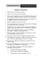
Embedded Controller TKS-G20-LN05 Rev.B Safety & Warranty 1. Read these safety instructions carefully. 2. Keep this user's manual for later reference. 3. Disconnect this equipment from any AC outlet before cleaning. Do not use liquid or spray detergents for cleaning. Use a damp cloth. 4. For pluggable equipment, the power outlet must be installed near the equipment and must be easily accessible. 5. Keep this equipment away from humidity. 6. Put this equipment on a firm surface during installation.
Embedded Controller TKS-G20-LN05 Rev.B d. The equipment does not work well, or you cannot get it to work according to the user’s manual. e. The equipment has been dropped and damaged. f. The equipment has obvious signs of breakage. 15. DO NOT LEAVE THIS EQUIPMENT IN AN ENVIRONMENT WHERE THE STORAGE TEMPERATURE IS BELOW -20°C (-4°F) OR ABOVE 55°C (131°F). IT MAY DAMAGE THE EQUIPMENT. FCC This device complies with Part 15 FCC Rules.
Embedded Controller TKS-G20-LN05 Rev.
Embedded Controller Chapter 1 TKS-G20-LN05 Rev.B General Information 1.1 Introduction................................................................ 1-2 1.2 Features .................................................................... 1-3 1.3 Specifications ............................................................ 1-4 Chapter 2 Hardware Installation 2.1 Dimension and I/O of TKS-G20-LN05 Rev.B............ 2-2 2.2 Location of Connectors and Jumpers of the Main Board ................................
Embedded Controller TKS-G20-LN05 Rev.B A.2 W83627DHG Watchdog Timer Initial Program ....A-7 Appendix B DIO B.1 DIO .......................................................................
Embedded Controller TKS-G20-LN05 Rev.
Embedded Controller TKS-G20-LN05 Rev.B 1.1 Introduction The newest Boxer series TKS-G20-LN05 Rev.B has been introduced by AAEON and it utilizes Intel® Atom™ processor. In this era of information explosion, the advertising of consumer products will not be confined to the family television, but will also spread to high-traffic public areas, like department stores, the bus, transportation station, the supermarket etc.
Embedded Controller TKS-G20-LN05 Rev.B 1.2 Features Intel® AtomTM D525 1.8 GHz Processor Intel® ICH8M Chipset DDR3 667/800 SODIMM x 1, Up To 4 GB CRT (VGA) Single View 2CH HD Audio Gigabit Ethernet x 2 2.5” SATA Hard Disk Drive Bay x 1 USB2.
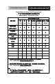
Embedded Controller TKS-G20-LN05 Rev.B 1.3 Specifications CPU Onboard Intel® Atom™ D525, 1.8 GHz Processor Chipset Intel® ICH8M System Memory 200-pin DDR3 SODIMM x1, Max. 4GB(DDR3 667/800) Display VGA D-SUB 15 x 1 Storage SSD Type 2 CompactFlash™ Slot x 1 Device HDD 2.5" Hard Disk Drive Bayx1 LAN 10/100/1000 Base-TX Ethernet, RJ-45 x 2 Wireless 802.
Embedded Controller TKS-G20-LN05 Rev.B Mounting Desktop or Wallmount (optional) Operating Temperature 32°F ~ 113°F (0°C ~ 45°C) Storage Temperature -40°F ~ 176°F (-40°C ~ 80°C) Anti-Vibration Anti-Shock 0.5g rms/ 5 ~ 500Hz/ random operation (Internal Hard Disk Drive active Module) 10G peak acceleration (11 msec. duration) (Hard Disk Drive Module) Certification EMC CE/FCC Class A Dimension 10" x 5.75" x 2.48" (254mm x 146mm x 63mm) Gross Weight Heavy duty steel (2.42 kg/ 5.
Embedded Controller TKS-G20-LN05 Rev.
Embedded Controller TKS-G20-LN05 Rev.B 2.1 Dimension and I/O of TKS-G20-LN05 Rev.
Embedded Controller TKS-G20-LN05 Rev.B 2.
Embedded Controller Solder Side Chapter 2 Quick Installation Guide 2 - 4 TKS-G20-LN05 Rev.
Embedded Controller TKS-G20-LN05 Rev.B 2.3 List of Jumpers The board has a number of jumpers that allow you to configure your system to suit your application. The table below shows the function of each of the board's jumpers: Label Function JP2 Auto Power Button Selection JP3 COM2 RI/+5/+12V Selection JP4 Clear CMOS 2.4 List of Connectors The board has a number of connectors that allow you to configure your system to suit your application.
Embedded Controller TKS-G20-LN05 Rev.
Embedded Controller TKS-G20-LN05 Rev.B 2.5 COM Port #2 RS-232/422/485 Selection (CN22) COM2 RS-232/422/485 selection for AAEON TKS series is set in BIOS setting as following: Entering BIOS Setting Menu: Choose "Integrated Peripherals Super IO device COM2 select". (Default setting is at "RS-232") Different devices implement the RS-232/422/485 standard in different ways. If you have problems with a serial device, check the pin assignments below for the connector.
Embedded Controller TKS-G20-LN05 Rev.B 3 RXD+ 4 N/C 5 TXD+ 6 N/C 7 RXD- 8 N/C / +5 Volt. / (+12 Volt.) 9 Ground 10 N/C RS-485 Mode Pin Signal Pin Signal 1 TXD- 2 N/C 3 N/C 4 N/C 5 TXD+ 6 N/C 7 N/C 8 N/C / +5 Volt. / (+12 Volt.) 9 Ground 10 N/C Note: Issue: COM port limitation for the speed test during the communication.
Embedded Controller TKS-G20-LN05 Rev.B 2.6 Digital I/O Connector (CN26) This connector offers 4-pair of digital I/O function. BIOS using the I2C Bus to read/write internal DIO registers and the Serial Bus address is 0x6E. The pin definitions are illustrated below: Pin Signal Pin Signal 1 DIO_IN0 2 DIO_IN1 3 DIO_IN2 4 DIO_IN3 5 DIO_OUT0 6 DIO_OUT1 7 DIO_OUT2 8 DIO_OUT3 9 +3.3 Volt. 10 Ground Note: The max. rating of Pin 1 ~ Pin 8 is 3.3V@8mA The max. rating of Pin 9 is 3.3V@0.
Embedded Controller TKS-G20-LN05 Rev.B 2.7 Hard Disk Installation Step 1: Unfasten the screws on the top of the heat-sink and you will see the inside of the system.
Embedded Controller TKS-G20-LN05 Rev.B Step 2: Unfasten the two screws on the front side and right side of the chassis. Step 3: Fasten the four HDD screws and black damper and then you can put the HDD in it.
Embedded Controller TKS-G20-LN05 Rev.B Step 4: Connect the HDD cables Step 5: Fasten the two screws on the front side and right side of the chassis.
Embedded Controller TKS-G20-LN05 Rev.B Step 6: Fasten the screws on the top of the heatsink.
Embedded Controller TKS-G20-LN05 Rev.B 2.8 PCIe Card Installation Step 1: Unfasten the screws on the top of the case and you will see the inside of the system. Step 2: Unfasten the HDD screws where is on the front side and right side of the chassis, and then take off the HDD bracket.
Embedded Controller TKS-G20-LN05 Rev.B HDD Bracket Step 3: Take off the HDD bracket and then you will see the top side of the main Board and find the PCIe slot shown as below for card installation. PCIe Slot Step 4: After done installing the mini card and HDD, please reverse the step 1 to 3 to finish the installation.
Embedded Controller TKS-G20-LN05 Rev.B 2.9 Accessory Installation Step 1: Unfasten the screws on the rear panel Step 2: You can see the inside placement of RAM, and CF card for installations.
Embedded Controller TKS-G20-LN05 Rev.B Step 2-1: Locate the memory module, insert the gold colored contact into the socket. Push the module down until it has been locked by two latches on two sides firmly Step 2-2: Unfasten the screws on the front panel. Insert the CompactFast card into the socket until it has been locked firmly, and then put the card bracket back and screws it up.
Embedded Controller TKS-G20-LN05 Rev.B Step 3: Fasten the screws on the rear panel.
Embedded Controller TKS-G20-LN05 Rev.B 2.10 Wallmount Kit Installation Get the brackets ready and fasten appropriate four screws on each bracket. After fastening the two brackets on the bottom lid, the wallmount kit installation has been finished.
Embedded Controller TKS-G20-LN05 Rev.
Embedded Controller 3.1 TKS-G20-LN05 Rev.B System Test and Initialization These routines test and initialize board hardware. If the routines encounter an error during the tests, you will either hear a few short beeps or see an error message on the screen. There are two kinds of errors: fatal and non-fatal. The system can usually continue the boot up sequence with non-fatal errors.
Embedded Controller 3.2 TKS-G20-LN05 Rev.B AMI BIOS Setup AMI BIOS ROM has a built-in Setup program that allows users to modify the basic system configuration. This type of information is stored in battery-backed CMOS RAM so that it retains the Setup information when the power is turned off. Entering Setup Power on the computer and press or immediately. This will allow you to enter Setup. Main Set the date, use tab to switch between date elements.
Embedded Controller TKS-G20-LN05 Rev.
Embedded Controller TKS-G20-LN05 Rev.B The TKS-G20-LN05 Rev.B comes with a DVD-ROM that contains all drivers and utilities that meet your needs.
Embedded Controller TKS-G20-LN05 Rev.B 4.1 Installation: Insert the TKS-G20-LN05 Rev.B DVD-ROM into the DVD-ROM Drive. And install the drivers from Step 1 to Step 5 in order. Step 1 – Install Chipset Driver 1. Click on the STEP1-CHIPSET folder and select the OS folder your system is 2. Double click on the .exe located in each OS folder 3. Follow the instructions that the window shows 4. The system will help you install the driver automatically Step 2 – Install VGA Driver 1.
Embedded Controller TKS-G20-LN05 Rev.B Step 4 – Install Audio Driver 1. Click on the STEP4-AUDIO folder and select the OS folder your system is 2. Double click on the Setup.exe located in each OS folder 3. Follow the instructions that the window shows 4. The system will help you install the driver automatically Step 5 – Install Wireless LAN Driver (Optional) 1. Click on the STEP5-WIRELESS LAN folder and select the OS folder your system is 2. Select the folder of Install_CD, and double click on the setup.
Embedded Controller TKS-G20-LN05 Rev.
Embedded Controller TKS-G20-LN05 Rev.B A.1 Programming TKS-G20-LN05 Rev.B utilizes W83627DHG-P chipset as its watchdog timer controller. Below are the procedures to complete its configuration and the AAEON intial watchdog timer program is also attached based on which you can develop customized program to fit your application.
Embedded Controller TKS-G20-LN05 Rev.B (3) Exit the W83627DHG config Mode. Undesired result may occur if the config Mode is not exited normally. (1) Enter the W83627DHG config Mode To enter the W83627DHG config Mode, two special I/O write operations are to be performed during Wait for Key state. To ensure the initial state of the key-check logic, it is necessary to perform two write operations to the Special Address port (2EH).
Embedded Controller = 010 TKS-G20-LN05 Rev.B Power LED pin is driven low. = 011 Power LED pin outputs 2Hz pulse with 50% duty cycle. = 100 Power LED pin outputs 1Hz pulse with 50% duty cycle. = 101 Power LED pin outputs 4Hz pulse with 50% duty cycle. = 110 Power LED pin outputs 0.25Hz pulse with 50% duty cycle. =111 Power LED pin outputs 0.25Hz pulse with 50% duty cycle.. Bit 4 Bit 3 Bit 2 : WDTO# count mode is 1000 times faster. =0 Disable. =1 Enable. : select WDTO# count mode.
Embedded Controller TKS-G20-LN05 Rev.B WatchDog Timer Register II (Index=F6h, Default=00h) Bit 7-0 = 0 x 00 Time-out Disable = 0 x 01 Time-out occurs after 1 second/minute = 0 x 02 Time-out occurs after 2 second/minutes = 0 x 03 Time-out occurs after 3 second/minutes ………………………………..
Embedded Controller =1 TKS-G20-LN05 Rev.B Force Watchdog Timer time-out event: this bit is self-clearing Bit 4 Bit 3-0 : Watchdog Timer Status. R/W =1 Watchdog Timer time-out occurred =0 Watchdog Timer counting : These bits select IRQ resource for Watchdog. Setting of 2 selects SMI.
Embedded Controller TKS-G20-LN05 Rev.B A.2 W83627DHG Watchdog Timer Initial Program Example: Setting 10 sec.
Embedded Controller TKS-G20-LN05 Rev.B ;/////////////////////////////////////////////////////////////////////////////////////////////// Dec dx Mov al,0f5h ;CRF5 (PLED mode register) Out dx,al Inc dx In al,dx And al,not 08h ;Set second as counting unit Out dx,al ;/////////////////////////////////////////////////////////////////////////////////////////////// Dec dx Mov al,0f6h ; CRF6 Out dx,al Inc dx Mov al,10 ;Set timeout interval as 10 sec.
Embedded Controller TKS-G20-LN05 Rev.
Embedded Controller TKS-G20-LN05 Rev.B B.1 DIO The F75111 provides one serial access interface, I2C Bus, to read/write internal registers. The address of Serial Bus is 0x6E (0110_1110) The related register for configuring DIO is list as follows: Configuration and Control Register – Index 01h Power-on default [7:0]=0000_1000b Bit Name R/W PWR Description 7 INIT R/W VSB3V Software reset for all registers including Test Mode registers. Users use only.
Embedded Controller TKS-G20-LN05 Rev.B Bit Name R/W PWR Description 7 GP27_OCTRL R/W VSB3V 6 GP26_OCTRL R/W VSB3V 5 GP25_OCTRL R/W VSB3V 4 GP24_OCTRL R/W VSB3V 3 GP23_OCTRL R/W VSB3V 2 GP22_OCTRL R/W VSB3V 1 GP21_OCTRL R/W VSB3V 0 GP20_OCTRL R/W VSB3V GPIO 27 output control. Set to 1 for output function. Set to 0 for input function (default). GPIO 26 output control. Set to 1 for output function. Set to 0 for input function (default). GPIO 25 output control.
Embedded Controller TKS-G20-LN05 Rev.B Bit Name R/W PWR Description 7 6 5 4 3 2 1 0 GP27_PSTS GP26_PSTS GP25_PSTS GP24_PSTS GP23_PSTS GP22_PSTS GP21_PSTS GP20_PSTS RO RO RO RO RO RO RO RO VSB3V VSB3V VSB3V VSB3V VSB3V VSB3V VSB3V VSB3V Read the GPIO27 data on the pin. Read the GPIO26 data on the pin. Read the GPIO25 data on the pin. Read the GPIO24 data on the pin. Read the GPIO23 data on the pin. Read the GPIO22 data on the pin. Read the GPIO21 data on the pin. Read the GPIO20 data on the pin.
Embedded Controller TKS-G20-LN05 Rev.
Embedded Controller TKS-G20-LN05 Rev.
Embedded Controller TKS-G20-LN05 Rev.
Embedded Controller TKS-G20-LN05 Rev.
Embedded Controller int TKS-G20-LN05 Rev.