Embedded Box TKS-P20-CV01 TKS-P20-CV01 Fanless Embedded Box Intel® Atom™ N2600 1.6 GHz Processor 1 GbE LAN, 5 USB2.0, 2 COM 1 VGA, 1 HDMI, 1 Mini Card or mSATA TKS-P20-CV01 Manual 1st Ed.
Embedded Box TKS-P20-CV01 Copyright Notice This document is copyrighted, 2013. All rights are reserved. The original manufacturer reserves the right to make improvements to the products described in this manual at any time without notice. No part of this manual may be reproduced, copied, translated, or transmitted in any form or by any means without the prior written permission of the original manufacturer. Information provided in this manual is intended to be accurate and reliable.
Embedded Box TKS-P20-CV01 Acknowledgments All other products’ name or trademarks are properties of their respective owners. AMI is a trademark of American Megatrends Inc. CompactFlash™ is a trademark of the Compact Flash Association. Microsoft Windows is a registered trademark of Microsoft Corp. Intel®, Atom™ are trademarks of Intel Corporation. PC/AT, PS/2, and VGA are trademarks of International Business Machines Corporation.
Embedded Box TKS-P20-CV01 Packing List Before you begin operating your PC, please make sure that the following materials are enclosed: 1 TKS-P20-CV01 Embedded Controller 1 DVD-ROM for manual (in PDF format) and drivers If any of these items should be missing or damaged, please contact your distributor or sales representative immediately.
Embedded Box TKS-P20-CV01 Safety & Warranty 1. Read these safety instructions carefully. 2. Keep this user's manual for later reference. 3. Disconnect this equipment from any AC outlet before cleaning. Do not use liquid or spray detergents for cleaning. Use a damp cloth. 4. For pluggable equipment, the power outlet must be installed near the equipment and must be easily accessible. 5. Keep this equipment away from humidity. 6. Put this equipment on a firm surface during installation.
Embedded Box TKS-P20-CV01 d. The equipment does not work well, or you cannot get it to work according to the user’s manual. e. The equipment has been dropped and damaged. f. The equipment has obvious signs of breakage. 15. DO NOT LEAVE THIS EQUIPMENT IN AN ENVIRONMENT WHERE THE STORAGE TEMPERATURE IS BELOW -20°C (-4°F) OR ABOVE 55°C (131°F). IT MAY DAMAGE THE EQUIPMENT. FCC This device complies with Part 15 FCC Rules.
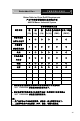
Embedded Box TKS-P20-CV01 Below Table for China RoHS Requirements 产品中有毒有害物质或元素名称及含量 AAEON Boxer/ Industrial System 有毒有害物质或元素 部件名称 铅 汞 镉 六价铬 多溴联苯 多溴二苯醚 (Pb) (Hg) (Cd) (Cr(VI)) (PBB) (PBDE) × ○ ○ ○ ○ ○ × ○ ○ ○ ○ ○ × ○ ○ ○ ○ ○ × ○ ○ ○ ○ ○ 硬盘 × ○ ○ ○ ○ ○ 电源 × ○ ○ ○ ○ ○ 印刷电路板 及其电子组件 外部信号 连接器及线材 外壳 中央处理器 与内存 O:表示该有毒有害物质在该部件所有均质材料中的含量均在 SJ/T 11363-2006 标准规定的限量要求以下。 X:表示该有毒有害物质至少在该部件的某一均质材料中的含量超出 SJ/T 11363-2006 标准规定的限量要求。 备注: 一、此产品所标示之环保使用期限,系指在一般正常使用状况下。 二、上述部件物
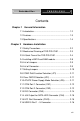
Embedded Box TKS-P20-CV01 Contents Chapter 1 General Information 1.1 Introduction................................................................ 1-2 1.2 Features .................................................................... 1-3 1.3 Specifications ............................................................ 1-4 Chapter 2 Hardware Installation 2.1 Safety Precautions .................................................... 2-2 2.2 Mechanical Drawing of TKS-P20-CV01 .................... 2-3 2.
Embedded Box TKS-P20-CV01 2.17 VGA Port Connector (CN12)................................... 2-17 2.18 HDMI Type C Connector (CN17) ............................ 2-18 2.19 Mini Card Slot (PCIE1) ............................................ 2-19 Chapter 3 AMI BIOS Setup 3.1 System Test and Initialization. .................................. 3-2 3.2 AMI BIOS Setup ........................................................ 3-3 Chapter 4 Driver Installation 4.1 Installation ....................................
Embedded Box TKS-P20-CV01 E.2 DIO Programming ..................................................E-2 E.3 Digital I/O Register.................................................E-3 E.4 Digital I/O Sample Program ...................................
Embedded Box TKS-P20-CV01 Chapter 1 General Information Chapter 1 General Information 1- 1
Embedded Box TKS-P20-CV01 1.1 Introduction The newest EmBox series TKS-P20-CV01 has been introduced by AAEON and it utilizes Intel® Atom™ processor. In this era of information explosion, the advertising of consumer products will not be confined to the family television, but will also spread to high-traffic public areas, like department stores, the bus, transportation station, the supermarket etc.
Embedded Box TKS-P20-CV01 1.2 Features Intel® Atom™ N2600 Processor up to 1.6GHz SODIMM DDR3 800MHz Memory up to 2 GB DIN RAIL and Fanless system Mini HDMI and VGA Support Gigabit Ethernet LAN x 1 USB2.
Embedded Box TKS-P20-CV01 1.3 Specifications CPU Onboard Intel® Atom™ N2600 Processor up to 1.6 GHz Chipset Intel® Atom™ N2600 + NM10 System Memory 204-pin DDR3 SODIMM x 1, Max. 2GB Display VGA D-SUB 15 x 1 Interface HDMI HDMI type C (Mini HDMI) x 1 Storage SSD mSATA x 1 (Half-size) Device HDD Optional by request LAN Gigabit Ethernet Wireless Optional by Mini Card USB Host USB 2.
Embedded Box TKS-P20-CV01 System Cooling Fanless Mounting Wallmount, DIN RAIL (optional) Dimension 4.7" x 2.3" x 4.3" (120mm x 59.5mm x 110mm) Gross Weight 2.2 lb (1 Kg) Net Weight 1.8 lb (0.82 Kg) Operating Temperature 32°F ~ 131°F (0°C ~ 55°C) Storage Temperature -40°F ~ 176°F (-40°C ~ 80°C) Operating Humidity Anti-Vibration Anti-Shock 0%~90% relative humidity, non-condensing 2 g rms/ 5 ~ 500Hz/ operation (mSATA) 20 G peak acceleration (11 msec.
Embedded Box TKS-P20-CV01 Chapter 2 Quick Installation Guide Chapter 2 Quick Installation Guide 2-1
Embedded Box TKS-P20-CV01 2.1 Safety Precautions Always completely disconnect the power cord from your board whenever you are working on it. Do not make connections while the power is on, because a sudden rush of power can damage sensitive electronic components. Always ground yourself to remove any static charge before touching the board. Modern electronic devices are very sensitive to static electric charges. Use a grounding wrist strap at all times.
Embedded Box TKS-P20-CV01 2.2 Mechanical Drawing of TKS-P20-CV01 Figure 2.1 Mechanical Drawing of TKS-P20-CV01 Dimension: 120mmx 59.
Embedded Box TKS-P20-CV01 2.3 A Quick Tour of the TKS-P20-CV01 Before you start to set up the TKS-P20-CV01, take a moment to become familiar with the locations and purposes of the controls, drives, connections and ports, which are illustrated in the figures below. When you place the TKS-P20-CV01 upright on the desktop, its front panel appears as Show in Figure 2-1. Front View Front View of the Point of Care Terminal (1) (6) (2) (3) (4) (7) (5) (8) (1). Power and HDD indicator LED (2).
Embedded Box TKS-P20-CV01 (6). COM1 & COM2 (7). Power Switch (8). Power DC-IN Remark: Power DC-IN with +12V or option wide range power board for 7-30V DC input Top Side View Top side View of the TKS-P20-CV01 (9) (10) (9). 4 bit Digital IO with VCC and ground pin (10).
Embedded Box TKS-P20-CV01 UBottom View Top side View of the TKS-P20-CV01 (11) (11).
Embedded Box TKS-P20-CV01 (12). DIN RAIL kit (optional) (13). Wall mount Kit (optional) Left side I/O View Figure 2.4 Left side View of the Point of Care Terminal (14) (14).
Embedded Box TKS-P20-CV01 2.4 Installing mSATA and RAM module Step 1: Unfasten the screws on the I/O cover from Left side Step 2: Remove the I/O cover then you can see the inside of system Step 3: Locate the memory module, Insert the gold colored contact into the Memory Socket. Push the module down, until it is firmly seated locking two latches on the sides. Step 4: Locate the mSATA module(same with mini card module), insert the gold colored contact into the Socket of mSATA mini card.
Embedded Box TKS-P20-CV01 2.5 List of Jumpers The board has a number of jumpers that allow you to configure your system to suit your application. The table below shows the function of each of the board's jumpers: Label Function JP1 COM2 RI/+5/+12V Selection JP2 Clear CMOS JP6 AT/ATX Power Mode Selection 2.6 List of Connectors The board has a number of connectors that allow you to configure your system to suit your application.
Embedded Box TKS-P20-CV01 CN17 HDMI Type C PCIE1 Mini Card 2.7 Setting Jumpers You configure your card to match the needs of your application by setting jumpers. A jumper is the simplest kind of electric switch. It consists of two metal pins and a small metal clip (often protected by a plastic cover) that slides over the pins to connect them. To “close” a jumper you connect the pins with the clip. To “open” a jumper you remove the clip. Sometimes a jumper will have three pins, labeled 1, 2 and 3.
Embedded Box TKS-P20-CV01 2.8 COM2 Pin8 Function Selection (JP1) +12V Ring JP1 Function 1-2 +12V 3-4 Ring (Default) 5-6 +5V +5V 2.9 Clear CMOS Selection (JP2) 1 2 3 1 2 3 Normal Clear CMOS JP2 Function 1-2 Normal (Default) 2-3 Clear CMOS 2.
Embedded Box TKS-P20-CV01 2.11 COM Port 1 Connector (CN) Pin Pin Name Signal Type 1 DCD1 IN 2 RX1 IN 3 TX1 OUT ±9V 4 DTR1 OUT ±9V 5 GND GND 6 DSR1 IN 7 RTS1 OUT 8 CTS1 IN 9 RI1 IN 2.
Embedded Box TKS-P20-CV01 RS-232 Pin Pin Name Signal Type Signal Level 1 DCD2 IN 2 RX2 IN 3 TX2 OUT ±9V 4 DTR2 OUT ±9V 5 GND GND 6 DSR2 IN 7 RTS2 OUT 8 CTS2 IN 9 RI2/+5V/+12V IN/ PWR +5V/+12V Pin Pin Name Signal Type Signal Level 1 RS422_TX- OUT ±5V 2 RS422_TX+ OUT 3 RS422_RX+ IN 4 RS422_RX- IN 5 NC 6 NC 7 NC 8 NC/+5V/+12V PWR 9 GND GND ±9V RS-422 ±5V +5V/+12V Chapter 2 Quick Installation Guide 2-13
Embedded Box TKS-P20-CV01 RS-485 Pin Pin Name Signal Type Signal Level 1 RS485_D- I/O ±5V 2 RS485_D+ I/O ±5V 3 NC 4 NC 5 NC 6 NC 7 NC 8 NC/+5V/+12V PWR +5V/+12V 9 GND GND 2.13 DIO Connector (CN2) Pin Pin Name Signal Type Signal Level 1 DIO0 I/O +3.3V 2 DIO1 I/O +3.3V 3 DIO2 I/O +3.3V 4 DIO3 I/O +3.3V 5 DIO_PWR PWR +3.
Embedded Box TKS-P20-CV01 Access Address based on SIO Location GPIO Port LDN6 (Pin #) Input Output GPIO1 2 Reg 0xD2, bit 0 Reg 0xD1, bit 0 GPIO2 3 Reg 0xD2, bit 1 Reg 0xD1, bit 1 GPIO3 4 Reg 0xD2, bit 2 Reg 0xD1, bit 2 GPIO4 5 Reg 0xD2, bit 3 Reg 0xD1, bit 3 2.14 +5V Output for SATA HDD Connector (CN4) +5V GND Pin Pin Name Signal Type Signal Level 1 +5V PWR +5V 2 GND GND 2.15 LPC Port Connector (CN10) LAD0 LAD1 LAD2 LAD3 +3.
Embedded Box TKS-P20-CV01 Pin Pin Name Signal Type Signal Level 1 LAD0 I/O +3.3V 2 LAD1 I/O +3.3V 3 LAD2 I/O +3.3V 4 LAD3 I/O +3.3V 5 +3.3V PWR +3.3V 6 LFRAME# IN 7 LRESET# OUT 8 GND GND 9 LCLK OUT 10 LDRQ0 IN 11 LDRQ1 IN 12 SERIRQ I/O +3.3V +3.3V 2.16 USB2.
Embedded Box TKS-P20-CV01 2.
Embedded Box TKS-P20-CV01 2.
Embedded Box TKS-P20-CV01 2.19 Mini Card Slot (PCIE1) Pin Pin Name Signal Type 1 PCIE_WAKE# IN 2 +3.3VSB/+3.3V PWR 3 NC 4 GND 5 NC 6 +1.5V 7 PCIE_CLK_REQ# 8 NC 9 GND 10 NC 11 PCIE_REF_CLK- 12 NC 13 PCIE_REF_CLK+ 14 NC 15 GND 16 NC 17 NC 18 GND 19 NC 20 W_DISABLE# OUT 21 GND GND Signal Level +3.3V GND PWR +1.5V IN GND DIFF DIFF GND GND +3.
Embedded Box TKS-P20-CV01 22 PCIE_RST# OUT 23 PCIE_RX-/ mSATA_RX+ DIFF 24 +3.3VSB/+3.3V PWR 25 PCIE_RX+/mSATA_RX- DIFF 26 GND GND 27 GND GND 28 +1.5V PWR 29 GND GND 30 SMB_CLK I/O 31 PCIE_TX-/mSATA_TX- DIFF 32 SMB_DATA I/O 33 PCIE_TX+/mSATA_TX+ DIFF 34 GND GND 35 GND GND 36 USB8_D- DIFF 37 GND GND 38 USB8_D+ DIFF 39 +3.3VSB/+3.3V PWR 40 GND GND 41 +3.3VSB/+3.
Embedded Box 46 NC 47 NC 48 +1.5V 49 NC 50 GND 51 NC 52 +3.3VSB/+3.3V TKS-P20-CV01 PWR +1.5V GND PWR +3.
Embedded Box TKS-P20-CV01 Below Table for China RoHS Requirements 产品中有毒有害物质或元素名称及含量 AAEON Main Board/ Daughter Board/ Backplane 有毒有害物质或元素 部件名称 铅 汞 镉 六价铬 多溴联苯 多溴二苯醚 (Pb) (Hg) (Cd) (Cr(VI)) (PBB) (PBDE) × ○ ○ ○ ○ ○ × ○ ○ ○ ○ ○ 印刷电路板 及其电子组件 外部信号 连接器及线材 O:表示该有毒有害物质在该部件所有均质材料中的含量均在 SJ/T 11363-2006 标准规定的限量要求以下。 X:表示该有毒有害物质至少在该部件的某一均质材料中的含量超出 SJ/T 11363-2006 标准规定的限量要求。 备注:此产品所标示之环保使用期限,系指在一般正常使用状况下。 Chapter 2 Quick Installation Guide 2-22
Embedded Box TKS-P20-CV01 Chapter 3 AMI BIOS Setup Chapter 3 AMI BIOS Setup 3-1
Embedded Box TKS-P20-CV01 3.1 System Test and Iinitialization These routines test and initialize board hardware. If the routines encounter an error during the tests, you will either hear a few short beeps or see an error message on the screen. There are two kinds of errors: fatal and non-fatal. The system can usually continue the boot up sequence with non-fatal errors. System configuration verification These routines check the current system configuration stored in the CMOS memory and BIOS NVRAM.
Embedded Box TKS-P20-CV01 complete unit when it finally runs down. 3.2 AMI BIOS Setup AMI BIOS ROM has a built-in Setup program that allows users to modify the basic system configuration. This type of information is stored in battery-backed CMOS RAM and BIOS NVRAM so that it retains the Setup information when the power is turned off. Entering Setup Power on the computer and press or immediately. This will allow you to enter Setup. Main Set the date, use tab to switch between date elements.
Embedded Box TKS-P20-CV01 Setup Menu Setup submenu: Main Options summary: (default setting) System Date Day MM:DD:YYYY Change the month, year and century. The ‘Day’ is changed automatically. System Time HH : MM : SS Change the clock of the system.
Embedded Box TKS-P20-CV01 Setup submenu: Advanced Options summary: (default setting) ACPI Settings System ACPI Parameters CPU Configuration CPU Configuration Parameters IDE Configuration IDE Device Options Settings USB Configuration USB Configuration Parameters COM Port Configuration Chapter 3 AMI BIOS Setup 3-5
Embedded Box TKS-P20-CV01 COM Port Configuration Parameters Digital IO Port Configuration DIO configuration H/W Monitor Monitor hardware status ACPI Settings Options summary: (default setting) Enabled Enable Hibernation Disabled Enabled or disabled hibernate (OS/S4 Sleep State).
Embedded Box TKS-P20-CV01 Suspend Disabled S1 only(CPU Stop Clock) ACPI Sleep State S3 only(Suspend to RAM) AUTO Select the ACPI state used for System Suspend Enabled Wake on Ring Disabled Enabled or disabled wake on ring function. RTC Wake Settings Enable system to wake from S5 using RTC alarm.
Embedded Box TKS-P20-CV01 Options summary: (default setting) Wake system with Fixed Disabled Time Enabled Enable or disable System wake on alarm event. Wake up time is setting by following settings. Wake up day 0-31 Select 0 for daily system wake up 1-31 for which day of the month that you would like the system to wake up Wake up hour 0-23 Wake up minute 0-59 Wake up second 0-59 Wake system with Disabled Dynamic Time Enabled Enable or disable System wake on alarm event.
Embedded Box TKS-P20-CV01 CPU Configuration Options summary: (default setting) Hyper-Threading Disabled Enabled En/Disable CPU Hyper-Threading function Execute Disable Bit Disabled Enabled En/Disable XD bit for supporting OS Limit CPUID Maximum Disabled Enabled Disabled for Windows XP Chapter 3 AMI BIOS Setup 3-9
Embedded Box CPU Power Management Configure CPU PPM parameters CPU Power Management Options summary: (default setting) EIST Disabled Enabled En/Disable Intel SpeedStep CPU C State Report Disabled Enabled Chapter 3 AMI BIOS Setup 3-10 TKS-P20-CV01
Embedded Box TKS-P20-CV01 Report C State support for ACPI OS IDE Configuration Options summary: (default setting) SATA Controller(s) Disabled Enabled En/Disable SATA controller Configure SATA as IDE AHCI Configure SATA controller operating as IDE/AHCI mode.
Embedded Box TKS-P20-CV01 USB Configuration Options summary: (default setting) Legacy USB Support Enabled Disabled Auto Enables BIOS Support for Legacy USB Support. When enabled, USB can be functional in legacy environment like DOS. AUTO option disables legacy support if no USB devices are connected.
Embedded Box TKS-P20-CV01 Forced FDD Hard Disk CD-ROM If Auto. USB devices less than 530MB will be emulated as Floppy and remaining as Floppy and remaining as hard drive. Forced FDD option can be used to force a HDD formatted drive to boot as FDD(Ex.
Embedded Box TKS-P20-CV01 Serial Port 1 Configuration Options summary: (default setting) Serial Port Disabled Enabled En/Disable specified serial port.
Embedded Box TKS-P20-CV01 Select a resource setting for Super IO device. Serial Port 2 Configuration Options summary: (default setting) Serial Port Disabled Enabled En/Disable specified serial port.
Embedded Box TKS-P20-CV01 IO=3E8h; IRQ=3,4,5,7,10,11,12; IO=2E8h; IRQ=3,4,5,7,10,11,12; Select a resource setting for Super IO device. Device Type RS232 RS422 RS485 Configure COM2 operated as RS232, RS422 or RS485.
Embedded Box Direction TKS-P20-CV01 Output Set GPIO1/GPIO2 as Input or Output GPIO3/GPIO4 Input Direction Output Set GPIO3/GPIO4 as Input or Output Output Level Hi Low Set GPIO Level when used as Output H/W Monitor Chapter 3 AMI BIOS Setup 3-17
Embedded Box Setup submenu: Chipset Options summary: (default setting) Host Bridge Host Bridge Parameters South Bridge South Bridge Parameters Chapter 3 AMI BIOS Setup 3-18 TKS-P20-CV01
Embedded Box TKS-P20-CV01 Host Bridge Options summary: (default setting) Fixed Graphics Memory 128MB Size 256MB Configure Fixed Graphics Memory Size IGFX - Boot Type Auto Detect CRT HDMI Select Primary boot display device Chapter 3 AMI BIOS Setup 3-19
Embedded Box South Bridge Options summary: (default setting) Onboard Devices Onboard devices parameters configurations MiniCard Function mSATA PCIe Switch miniCard function to mSATA or PCIe PCIe MiniCard Slot Auto Enabled Disabled Control the PCI Express Root Port.
Embedded Box High Precision Timer TKS-P20-CV01 Enabled Disabled Enable or Disable the High Precision Event Timer SLP_S4 Assertion Width 1-2 Seconds 2-3 Seconds 3-4 Seconds 4-5 Seconds Select a minimum assertion width of the SLP_S4# signal Restore AC Power Loss Power On Power Off Last State Select AC power state when power is re-applied after a power failure.
Embedded Box TKS-P20-CV01 Onboard Devices Options summary: (default setting) Azalia Controller Disabled HD Audio Enable or disabled Azalia controller LAN Controller Disabled Enabled Enable or disable Realtek R8111E PCIE Lan Device SMBus Controller Disabled Enabled Enable or Disable OnChip SMBus Controller Chapter 3 AMI BIOS Setup 3-22
Embedded Box TKS-P20-CV01 Setup submenu: Boot Options summary: (default setting) Quiet Boot Disabled Enabled En/Disable showing boot logo. Launch LAN PXE OpROM Disabled Enabled En/Disable PXE boot for RTL8111E LAN Boot Option #X/ XXXX Drive BBS Priorities The order of boot priorities.
Embedded Box BBS Priorities Options summary: (default setting) Boot Option #x Disabled Device name Sets the system boot order Chapter 3 AMI BIOS Setup 3-24 TKS-P20-CV01
Embedded Box TKS-P20-CV01 Setup submenu: Security Options summary: (default setting) Administrator Password/ Not set User Password You can install a Supervisor password, and if you install a supervisor password, you can then install a user password. A user password does not provide access to many of the features in the Setup utility. Install the Password: Press Enter on this item, a dialog box appears which lets you enter a password. You can enter no more than six letters or numbers.
Embedded Box TKS-P20-CV01 required at boot time, or when the user enters the Setup utility. Removing the Password: Highlight this item and type in the current password. At the next dialog box press Enter to disable password protection. HDD Security Options summary: (default setting) Set User Password/ Not set Set Master Password You can install a Master and User password. Before booting to OS, HDD will be set to frozen state.
Embedded Box TKS-P20-CV01 entered while system booting. Install the Password: Press Enter on this item, a dialog box appears which lets you enter a password. You can enter no more than six letters or numbers. Press Enter after you have typed in the password. A second dialog box asks you to retype the password for confirmation. Press Enter after you have retyped it correctly. The password is required at boot time, or when the user enters the Setup utility.
Embedded Box TKS-P20-CV01 Setup submenu: Exit Options summary: (default setting) Save Changes and Reset Reset the system after saving the changes Discard Changes and Reset Reset system setup without saving any changes Restore Defaults Restore/Load Default values for all the setup options.
Embedded Box TKS-P20-CV01 Restore the User Defaults to all the setup options Chapter 3 AMI BIOS Setup 3-29
Embedded Box TKS-P20-CV01 Chapter 4 Driver Installation .
Embedded Box TKS-P20-CV01 The TKS-P20-CV01 comes with an AutoRun DVD-ROM that contains all drivers and utilities that can help you to install the driver automatically. Insert the driver DVD, the driver DVD-title will auto start and show the installation guide. If not, please follow the sequence below to install the drivers.
Embedded Box 4.1 TKS-P20-CV01 Installation: Insert the TKS-P20-CV01 DVD-ROM into the DVD-ROM drive. And install the drivers from Step 1 to Step 6 in order. Step 1 – Install Chipset Driver 1. Click on the STEP1-CHIPSET folder and select the OS folder your system is 2. Double click on the infinst_autol_1034.exe file located in each OS folder 3. Follow the instructions that the window shows 4. The system will help you install the driver automatically Step 2 – Install VGA Driver For Windows® 7 1.
Embedded Box TKS-P20-CV01 2. Install IEMGD Double click on the SETUP.
Embedded Box TKS-P20-CV01 If you want to update driver, please uninstall driver first. Uninstall IEMGD 1. Double click on the SETUP.exe 2. Follow the instructions that the window shows 3.
Embedded Box TKS-P20-CV01 Step 3 – Install AHCI Driver Please refer to the Appendix D AHCI Setting Step 4 – Install LAN Driver 1. Click on the STEP4-LAN folder and select the OS folder your system is 2. Double click on the setup.exe file located in each OS folder 3. Follow the instructions that the window shows 4. The system will help you install the driver automatically Step 5 – Install Audio Driver 1. Click on the STEP5-AUDIO folder and select the OS folder your system is 2. Double click on the Setup.
Embedded Box 4. TKS-P20-CV01 The system will help you install the driver automatically For Windows® 7: 1. Create a password for Administrator account. 2.
Embedded Box TKS-P20-CV01 3. Reboot and Administrator login. 4. To run patch.bat with [Run as administrator].
Embedded Box TKS-P20-CV01 Appendix A Programming the Watchdog Timer Appendix A Programming the Watchdog Timer A-1
Embedded Box TKS-G21-CV05 A.1 Watchdog Timer Registers Table 1 : Watch dog relative IO address Default Value I/O Base Address Note I/O Base address for Watchdog operation. 0xA00 This address is assigned by SIO LDN7, register 0x60‐0x61.
Embedded Box TKS-P20-CV01 A.
Embedded Box TKS-G21-CV05 AaeonWDTEnable(); } ******************************************************************************* ******************************************************************************* // Procedure : AaeonWDTEnable VOID AaeonWDTEnable (){ WDTEnableDisable(1); } // Procedure : AaeonWDTConfig VOID AaeonWDTConfig (byte Counter, BOOLEAN Unit){ // Disable WDT counting WDTEnableDisable(0); // Clear Watchdog Timeout Status WDTClearTimeoutStatus(); // WDT relative parameter setting WDTParamet
Embedded Box TKS-P20-CV01 WDTSetBit(TimerReg, PSWidthBit, PSWidthVal); // Watchdog WDTRST# Enable WDTSetBit(DevReg, WDTRstBit, WDTRstVal); } VOID WDTClearTimeoutStatus(){ WDTSetBit(TimerReg, StatusBit, 1); } ******************************************************************************* ******************************************************************************* VOID WDTWriteByte(byte Register, byte Value){ IOWriteByte(WDTAddr+Register, Value); } byte WDTReadByte(byte Register){ return IOReadByte(WDTAd
Embedded Box TKS-P20-CV01 Appendix B I/O Information Appendix B I/O Information B-1
Embedded Box B.
Embedded Box TKS-P20-CV01 Appendix B I/O Information B-3
Embedded Box B.
Embedded Box TKS-P20-CV01 B.
Embedded Box Appendix B I/O Information B-6 TKS-P20-CV01
Embedded Box TKS-P20-CV01 B.
Embedded Box TKS-P20-CV01 Appendix C Mating Connector Appendix C Mating Connector C - 1
Embedded Box TKS-P20-CV01 C.1 List of Mating Connectors and Cables The table notes mating connectors and available cables.
Embedded Box CN11 USB Port 5 CATCH CN12 Analog CRT Display ASTRON CN13 USB Port 3 CATCH CN14 USB Port 4 CATCH CN15 CN16 18-bit LVDS Output USB Port 1 and 2 E-Call TechBest TKS-P20-CV01 1201-700-05S USB Port 1700050207 Cable HDLH-B15-CF N/A HN1T-1-R USB Port 1201-700-05S Cable USB Port 1201-700-05S Cable 0110-01-553-20 N/A 0 KS-002D-ANB( N/A 2.
Embedded Box TKS-P20-CV01 Appendix D AHCI Setting Appendix D AHCI Setting D-1
Embedded Box TKS-P20-CV01 D.1 Setting AHCI OS installation to SETUP AHCI Mode Step 1: Copy below files from “Driver CD -> STEP3-AHCI \WinXP_32” and to diskette. Step 2: Connect the USB Floppy drive to the board and insert the diskette from previous step.
Embedded Box TKS-P20-CV01 Step 4: Configure DVD/CD-ROM drive as the first boot device.
Embedded Box TKS-P20-CV01 Step 6 – Boot to DVD/CD-ROM device to install OS Step 7 – Press “F6” to install AHCI driver Step 8 – Press “S” to install AHCI driver Step 9 – Choose “Intel(R) ICH7R/DH SATA AHCI Controller” Step 10 – Windows Setup will display the controller name you selected in previous step and continue to install OS when ”ENTER” pressed.
Embedded Box TKS-P20-CV01 Appendix E Digital I/O Ports Appendix E Digital I/O Ports E-1
Embedded Box TKS-P20-CV01 E.1 Electrical Specifications for Digital I/O Ports Table 1 : Digital Input/Output Pin Electrical Specification Input Threshold Pin Type Voltage Output Voltage Low High Low High DIO1 I/O 0.8 2.0 0 3.3 DIO2 I/O 0.8 2.0 0 3.3 DIO3 I/O 0.8 2.0 0 3.3 DIO4 I/O 0.8 2.0 0 3.3 Note Note: All DIO pins are 5V tolerance in input mode. E.2 DIO Programming TKS-P20-CV01 utilizes FINTEK F81801U chipset as its Digital I/O controller.
Embedded Box TKS-P20-CV01 E.
Embedded Box TKS-P20-CV01 E.
Embedded Box TKS-P20-CV01 // Input : // Example, Set Digital I/O Pin 2 to high level AaeonSetOutputLevel(Pin2Bit, PinHigh); } ************************************************************************** ************************************************************************** Boolean AaeonReadPinStatus(byte PinBit){ Boolean PinStatus ; PinStatus = SIOBitRead(DIOLDN, StatusReg, PinBit); Return PinStatus ; } VOID AaeonSetOutputLevel(byte PinBit, byte Value){ ConfigDioMode(PinBit, OutputPin); SIOBitSet(DIOL
Embedded Box TKS-P20-CV01 SIOEnterMBPnPMode(); SIOSelectLDN(LDN); IOWriteByte(SIOIndex, Register); TmpValue = IOReadByte(SIOData); TmpValue &= ~(1 << BitNum); TmpValue |= (Value << BitNum); IOWriteByte(SIOData, TmpValue); SIOExitMBPnPMode(); } VOID SIOByteSet(byte LDN, byte Register, byte Value){ SIOEnterMBPnPMode(); SIOSelectLDN(LDN); IOWriteByte(SIOIndex, Register); IOWriteByte(SIOData, Value); SIOExitMBPnPMode(); } ************************************************************************** ****** Appen