
Manual


3.0 Installation Instructions
Consult the product drawing that was submitted for this order
before proceeding.
3.1 Space Requirements
A minimum of 24" clear space must be allowed on all sides of the
collector that do not include the access ladder or ductwork. The side
where the access ladder is located requires a minimum clear space of
46". For Walk-in Plenum units a minimum of 48” must be allowed on
the manifold side. More space may be required where inlet or outlet
ductwork and the explosion vent is located. For standard plenum top
access units, be sure to allow adequate height for removal of bags
and cages.
3.2 Foundations and Anchoring
The foundation must be designed to be adequate to support the
collector’s operating weight (see Section 9), seismic, wind and snow
loads (if any), collected dust, and any optional equipment, in
accordance with appropriate codes. Secure all anchor bolts to ensure
that the collector is firmly attached to the foundation. Base plates on
columns may require grouting after leveling. Multiple module units,
operating at elevated temperatures, may require expansion provisions
in the structural supports (see erection drawings for details).
4
tank/pulse pipe assembly. Each pulse valve serves twelve bags.
Pulse pipes are 1
1
2 ", schedule 40 pipe and have a quick
disconnect coupling and a pinned end.
Standard collectors are primed and finish painted on the exterior with
high solids alkyd enamel. Interior surfaces have a prime coat. High
temperature collectors have one coat of zinc rich primer. Special paint
coatings are available as an option.
Some of the more common optional features available with the
Millennium include pressure demand cleaning, explosion vents, inlet
adapter plates, an arrangement to permit installation of up to 4"
thickness insulation at the destination job site, walk-in plenum, trough
hopper, high temperature features, and various ancillary components.
Consult the P.O. and submittal documents for what is included with
the specific order.
3.3 General Erection Procedure
1. Spreader bars must be used at all times when handling the
Millennium to prevent any possibility of damage. These shall be
connected to the lifting lugs provided on the Millennium for this
purpose. Only personnel experienced in rigging and handling
heavy equipment shall be employed to erect the Millennium.
Refer to proper drawings for specific lifting instructions for
module configuration.
2. All modules shall be separately positioned on the structure and
adjacent to one another in the order in which they will be joined
together. (See Section 1.4)
3. All joints between one of the end modules and adjacent modules
shall be prepared for connection to one another. This applies to all
perimeter and internal connecting flanges. Ensure the following:
• All flanges are flat and planar. Correct any bending, warping, or
denting that may have occurred when the modules were being
transported or handled.
• All flanges are clean and free from debris, contamination and
discontinuities of any kind, such as weld or paint splatter, mud,
rust, oil, or grease.
• All bolt holes are correctly aligned.
4. Caulk all connecting surfaces using the caulking compound
supplied. On standard units, this is a butyl caulk. Silicone caulk is
supplied on units rated to 400°F. See Figure 4 for the method of
applying caulk to a housing flange.
CAUTION: Particular caution must be exercised when sealing the
internal connection between the tube sheets in adjacent modules.
The tube sheet is the horizontal plate through which the filters are
inserted and which forms the barrier between the clean and dirty air
sides of the collector. The flange of the tube sheet between modules
is provided with a double row of bolt holes. Each row of holes shall
be caulked as shown in Figure 4. It is only necessary to apply caulk
to one face of each joint. Apply the caulk liberally to ensure an
effective seal.
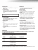
Figure 3
Pulse Pipe
Clean Air
Plenum
Solenoid
Valve
Air Hose
Compressed Air Surge Tank
Diaphragm Pulse Valve