
Manual


5. When the caulking has been applied, and before it dries, join the
modules and bolt them together, placing the bolts and washers in
every hole provided. Tighten the bolts fully.
6. Repeat the procedure described in Section 3.3, steps 3 through 5,
until all of the modules have been connected.
NOTE: Depending on the availability of space, the ability to
maneuver equipment, and the size of the collector, it may be
necessary to modify this erection procedure. This may be done
at the discretion of the rigging contractor after thoughtful
consideration and consultation with an AAF representative.
3.4 Ductwork
Connect the inlet duct to the drilled and flanged inlet(s) of the
collector. Connect the clean air duct to the drilled collector outlet.
Ductwork should be of sufficient gauge to withstand the system
design pressure and should be independently supported. The
Millennium is not designed to support ductwork. Hot gas ducts
may require expansion joints to prevent expansion loads on collector
inlets and outlets.
Close coupling a duct elbow to the collector inlet will result in an
uneven velocity profile. This condition may result in less than optimum
collector performance. A straight run of duct with a length equal to
three to four duct diameters immediately before the inlet will provide
an adequate airflow distribution to the inlet.
When attaching inlet and outlet ducts, caulk the flanges appropriately
to ensure that no leakage will occur during operation.
3.5 Ladder and Handrail Assembly
It is necessary to install the access ladder and handrails after
assembling the collector. The first step is to position the handrails
into place and secure them with bolts at the posts. The kick plates
are integral to the handrail sections. Refer to the installation drawings
supplied with the equipment for details.
The access ladder assembly is complete with a safety cage and
mounting brackets. Bolt (or weld) the ladder to the collector housing,
as shown in the installation drawing. The ladder assembly has
mounting brackets which attach to the housing and to the
hopper/housing flange. Ladder mounting brackets may be
bolted (or field welded) to the collector.
3.6 Electrical Controls and Wiring
WARNING: Potential shock hazard. Disconnect power before
servicing. Only qualified electrical personnel should work on
this system.
The standard Millennium dust collector is supplied with electrical
solenoid valves mounted in a NEMA 4 enclosure installed adjacent
to the pressure manifold, and a pulse/timer control (normally one
control system is supplied for a complete unit). As previously
mentioned, a number of control and wiring options are available
with the Millennium. In lieu of the standard offering, your Millennium
may be supplied with a pressure demand control, or NEMA 9 rated
solenoid enclosures. Consult the contract drawings for details.
Always mount the control enclosure in an accessible location.
Control wiring must then be field installed between the solenoid
valves in the enclosure adjacent to the pressure manifold and the
timer output terminals in the control enclosure, as shown on the
electrical connection diagram. Refer to the drawing supplied with
the equipment for details. All electrical wiring material and labor will
be supplied by others.
Figure 5.
Control Board
without module
Control Board
with module
5
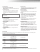
Figure 4
Bolt Hole
Sealant Bead
Housing or Hopper Flange