CB SERIES Condensing Units Installation, Operation & Maintenance WARNING WARNING QUALIFIED INSTALLER FOR YOUR SAFETY Improper installation, adjustment, alteration, service or maintenance can cause property damage, personal injury or loss of life. Startup and service must be performed by a Factory Trained Service Technician. A copy of this IOM should be kept with the unit. Do not store or use gasoline or other flammable vapors and liquids in the vicinity of this or any other appliance.
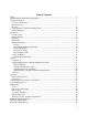
Table of Contents Safety .............................................................................................................................................. 5 CB Base Model and Features Description ...................................................................................... 8 General Description ........................................................................................................................ 9 Codes and Ordinances...................................................
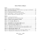
Index of Tables and Figures Tables: Table 1 - Recommended Elevation Minimums ............................................................................ 12 Table 2 - Predetermined Line sizes for CB units with two step compressors and R-410A .......... 20 Table 3 - Sub-cooling and Superheat ............................................................................................ 22 Table 4 - Performance Testing Air Flow Setpoints ......................................................................
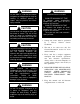
Safety Attention should be paid to the following statements: NOTE - Notes are intended to clarify the unit installation, operation and maintenance. CAUTION - Caution statements are given to prevent actions that may result in equipment damage, property damage, or personal injury. WARNING - Warning statements are given to prevent actions that could result in equipment damage, property damage, personal injury or death.
WARNING During installation, testing, servicing and troubleshooting of the equipment it may be necessary to work with live electrical components. Only a qualified licensed electrician or individual properly trained in handling live electrical components shall perform these tasks. Standard NFPA-70E, an OSHA regulation requiring an Arc Flash Boundary to be field established and marked for identification of where appropriate Personal Protective Equipment (PPE) be worn, should be followed.
WARNING Do not work in a closed area where refrigerant or nitrogen gases may be leaking. A sufficient quantity of vapors may be present and cause injury or death. CAUTION Do not clean DX refrigerant coils with hot water or steam. The use of hot water or steam on refrigerant coils will cause high pressure inside the coil tubing and damage to the coil. CAUTION To prevent damage to the unit, do not use acidic chemical coil cleaners. Do not use alkaline chemical coil cleaners with a pH value greater than 8.
CB Base Model and Features Description Model/Feature Number CB Series and Generation - B - Design Sequence 060 Unit Size - 3 - Voltage BASE MODEL SERIES AND GENERATION CB REVISION B = Design Sequence UNIT SIZE 024 = 24 MBH - 2 Ton - Vertical Discharge 036 = 36 MBH - 3 Ton - Vertical Discharge 048 = 48 MBH - 4 Ton - Vertical Discharge 060 = 60 MBH - 5 Ton - Vertical Discharge VOLTAGE 1 = 230V/1Φ/60Hz 2 = 230V/3Φ/60Hz 3 = 460V/3Φ/60Hz 4 = 575V/3Φ/60Hz 8 = 208V/3Φ/60Hz 9 = 208V/1Φ/60Hz COMPRESSOR TYP
General Description AAON® CB Series condensing units have been designed for outdoor installation only. Startup and service must be performed by a Factory Trained Service Technician. WARNING Coils and sheet metal surfaces present sharp edges and care must be taken when working with equipment. WARNING Improper installation, adjustment, alteration, service or maintenance can cause property damage, personal injury or loss of life. Startup and service must be performed by a Factory Trained Service Technician.
Direct Expansion (DX) Condensing Units CB Series condensing units are factory assembled and wired, including a full charge of R-410A refrigerant for up to 25 feet of line set. Systems with the modulating hot gas reheat option will require refrigerant to be field added because of the additional refrigerant components and piping associated with the system. for at least 24 hours. This will give the crankcase heater time to clear any liquid accumulation out of the compressor before it is required to run.
Installation AAON equipment has been designed for quick and easy installation. valves. At least two feet of clearance on this corner of the unit is recommended for service. Locating Unit CB Series condensing units are designed for outdoor application and placement at ground level or on a rooftop. Units must be placed on a level and solid foundation that can support the unit’s weight.
blow toward windows less than 25 feet away. any damage to the cabinet, coil or condensing fans. Heat pumps require special location consideration in areas where snow accumulation can become an obstruction and in areas with prolonged continuous subfreezing temperatures. Heat pump unit bases are cutout under the outdoor coil to permit drainage of frost accumulation. The unit must be situated to permit free unobstructed drainage of the defrost water and ice.
electrically grounded in accordance with local codes, or in the absence of local codes, the current National Electric Code, ANSI/NFPA 70 or the current Canadian Electrical Code CSA C22.1. Note: Units are factory wired for 208V, 230V, 460V or 575V. In some units, the 208V and 230V options may also be provided in single or three phase configurations. The transformer configuration must be checked by a qualified technician prior to startup. Wire power leads to the unit terminal block or compressor contactor.
Wire control signals to the unit’s low voltage terminal block located in the controls compartment. If any factory installed wiring must be replaced, use a minimum 105°C type AWM insulated conductors. Thermostat If a thermostat is used for unit control, thermostat should be located on an inside wall 4-5 feet above the floor where it will not be subjected to drafts, sun exposure, or heat from electrical fixtures or appliances. Follow thermostat manufacturer’s instructions for general installation procedure.
Determining Refrigerant Line Size CAUTION Line sizes must be selected to meet actual installation conditions, not simply based on the connection sizes at the condensing unit or air handling unit. The piping between the condenser and low side must ensure: 1. Minimum pressure drop, and 2. Continuous oil return, and 3.
Liquid Line Routing Care should be taken with vertical risers. When the system is shut down, gravity will pull liquid down the vertical column, and back to the condenser when it is below the evaporator. This could potentially result in compressor flooding. A check valve can be installed in the liquid line where the liquid column rises above the condenser to prevent this. The liquid line is typically pitched along with the suction line, or hot gas line, to minimize the complexity of the configuration.
A double suction riser can be applied to the situation of part load operation with a suction riser. A double suction riser is designed to return oil at minimum load while not incurring excessive frictional losses at full load. A double suction riser consists of a small diameter riser in parallel with a larger diameter riser, and a trap at the base of the large riser.
When installing hot gas bypass risers, an oil drip line must be provided at the lowest point in the system. The oil drip line must be vertical, its diameter should be the same as the diameter of the riser, and it should be 1 foot long. Install a sight glass in the oil drip line for observation. Run an oil return line, using 1/8 inch capillary tube, 10 feet in length, from the oil drip line to the suction line.
The liquid lines have been chosen to maintain velocities between 100 and 350 fpm. The suction line diameters are selected to limit velocities to a 4,000 fpm maximum, while a minimum velocity restriction is imposed by the ability to entrain oil up vertical suction risers (ASHRAE Handbook - Refrigeration). Acceptable pressure loss criteria are applied to each of the lines: The total equivalent length of the liquid line available is determined such that 3°F of liquid subcooling remain at the TXV.
Table 2 - Predetermined Line sizes for CB units with two step compressors and R-410A Model CB-024 CB-036 CB-048 CB-060 Connection Sizes Liquid Suction Hot Gas 3/8” 3/4” 3/8” 3/8” 3/4” 3/8” 3/8” 7/8” 1/2” 3/8” 7/8” 1/2” Liquid 3/8” 3/8” 1/2” 1/2” Predetermined Line Size Suction HGBP* 3/4” 3/8” 3/4” 3/8” 7/8” 1/2” 7/8” 1/2” HGRH** 3/8” 1/2” 1/2” 1/2” * Hot Gas Bypass line ** Hot Gas Reheat line Figure 2 - Riser height versus total equivalent line length Note: Figure 2 is for R-410A split system applicat
Startup (See back of the manual for startup form.) WARNING Improper installation, adjustment, alteration, service or maintenance can cause property damage, personal injury or loss of life. Installation and service must be performed by a trained, qualified installer. WARNING Electric shock hazard. Shut off all electrical power to the unit to avoid shock hazard or injury from rotating parts.
Units equipped with hot gas reheat must be charged with the hot gas valves closed while the unit is in cooling mode. After charging, unit should be operated in reheat (dehumidification) mode to check for correct operation. Checking Evaporator Superheat Measure the temperature of the suction line close to the compressor. After adding or removing charge the system must be allowed to stabilize, typically 10-15 minutes, before making any other adjustments.
Correct an overcharged system by reducing the amount of refrigerant in the system to lower the sub-cooling. CAUTION DO NOT OVERCHARGE! Refrigerant overcharging leads to excess refrigerant in the condenser coils resulting in elevated compressor discharge pressure. The system is undercharged if the superheat is too high and the sub-cooling is too low Correct an undercharged system by adding refrigerant to the system to reduce superheat and raise sub-cooling.
Table 5 - R-410A Refrigerant Temperature-Pressure Chart °F 20 21 22 23 24 25 26 27 28 29 30 31 32 33 34 35 36 37 38 39 40 41 42 43 44 45 46 24 PSIG 78.3 80.0 81.8 83.6 85.4 87.2 89.1 91.0 92.9 94.9 96.8 98.8 100.9 102.9 105.0 107.1 109.2 111.4 113.6 115.8 118.1 120.3 122.7 125.0 127.4 129.8 132.2 °F 47 48 49 50 51 52 53 54 55 56 57 58 59 60 61 62 63 64 65 66 67 68 69 70 71 72 73 PSIG 134.7 137.2 139.7 142.2 144.8 147.4 150.1 152.8 155.5 158.2 161.0 163.8 166.7 169.6 172.5 175.4 178.4 181.5 184.5 187.
Operation Unit operations should be controlled with thermostat, or unit controller, never at the main power supply, except for emergency, servicing, or complete shutdown of the unit. Thermostat Operation Heating Thermostat system switch - "Heat" Thermostat fan switch - "Auto" or "On" Thermostat temperature set to desired point. Cooling Thermostat system switch - "Cool" Thermostat fan switch - "Auto" or "On" Thermostat temperature set to desired point.
High Voltage Terminals A1 & A2 Alarm Relay Out M1 & M2 Contactor L1 Control Voltage N L2 Control Voltage L U1 & U2 Digital Unloader Solenoid V1 & V2 Vapor Injection Solenoid WARNING Figure 3 - Variable Capacity Compressor Controller Low Voltage Terminals 24COM Module Common 24VAC Module Power C1 & C2 Demand Input P1 Pressure Common P2 Pressure Input P3 Pressure Power 5VDC P4 Pressure Shield P5 & P6 Pressure Output T1 & T2 Discharge Temperature Sensor To avoid damaging the compressor controller, DO NOT con
Figure 4 - Compressor Controller Flash Code Details °C -40 -35 -30 -25 -20 -15 -10 -5 0 5 10 15 20 25 30 35 40 45 50 55 60 65 70 Table 7 - Thermistor Temperature vs. Resistance Values °F kΩ °C °F -40 2889.60 75 167 -31 2087.22 80 176 -22 1522.20 85 185 -13 1121.44 90 194 -4 834.72 95 203 5 627.28 100 212 14 475.74 105 221 23 363.99 110 230 32 280.82 115 239 41 218.41 120 248 50 171.17 125 257 59 135.14 130 266 68 107.44 135 275 77 86.00 140 284 86 69.28 145 293 95 56.16 150 302 104 45.81 155 311 113 37.
Low Ambient Options The condenser fan cycling option is used to operate a refrigerant system down to 35°F outside air temperature. As the ambient temperature drops, the condenser becomes more effective therefore lowering the head pressure. When the head pressure gets too low there will be insufficient pressure to operate the expansion valve properly.
used. In either case, the tool applied in the direction of the surfaces can be easily damaged bent over) if the tool is applied fins. should be fins. Coil (fin edges across the Use of a water stream, such as a garden hose, against a surface loaded coil will drive the fibers and dirt into the coil. This will make cleaning efforts more difficult. Surface loaded fibers must be completely removed prior to using low velocity clean water rinse.
may be beneath any soils, grease or dirt; therefore, these barriers must be removed prior to application of this product. As in all surface preparation, the best work yields the best results. Apply CHLOR*RID DTS - Apply directly onto the substrate. Sufficient product must be applied uniformly across the substrate to thoroughly wet out surface, with no areas missed. This may be accomplished by use of a pump-up sprayer or conventional spray gun.
Refrigerant Piping Diagrams Figure 5– A/C only piping, AHU above CU 31
Figure 6 – A/C only piping, AHU below CU 32
Figure 7 – Modulating hot gas reheat piping, AHU above CU 33
Figure 8 – Modulating hot gas reheat piping, AHU below CU 34
Figure 9 – Hot gas bypass piping, AHU above CU 35
Figure 10 – Hot gas bypass piping, AHU below CU 36
Figure 11 – Modulating hot gas reheat with hot gas bypass piping, AHU above CU 37
Figure 12 – Modulating hot gas reheat with hot gas bypass piping, AHU below CU 38
Figure 13 – Heat pump piping, AHU above CU 39
Figure 14 – Heat pump piping, AHU below CU 40
Figure 15 – Heat pump with modulating hot gas reheat piping, AHU above CU 41
Figure 16 – Heat pump with modulating hot gas reheat, AHU below CU 42
CB Series Startup Form Date:______________ Job Name:_____________________________________________________________________ Address:______________________________________________________________________ Model Number:_________________________________________________________________ ______________________________________________________________________________ Serial Number:_____________________________________________ Tag:_______________ Startup Contractor:______________________________________________________
Refrigeration System 1 - Heating Mode (Heat Pump Only) Saturated Line Pressure Temperature Temperature Discharge Suction Liquid Sub-cooling Superheat Air-Cooled Condenser Fan Alignment_____ Number 1 Check Rotation_____ hp L1 Nameplate Amps________ L2 L3 Maintenance Log This log must be kept with the unit. It is the responsibility of the owner and/or maintenance/service contractor to document any service, repair or adjustments.
Literature Change History June 2013 New installation and operation manual
AAON 2425 South Yukon Ave. Tulsa, OK 74107-2728 Phone: 918-583-2266 Fax: 918-583-6094 www.aaon.com CB Series Installation, Operation & Maintenance R57611 · Rev. - · 130603 (ACP J00187) It is the intent of AAON to provide accurate and current product information. However, in the interest of product improvement, AAON reserves the right to change pricing, specifications, and/or design of its product without notice, obligation, or liability. Copyright © AAON, all rights reserved throughout the world.