
Manual


27
Table 2 - Auxiliary Electric Heating Capacities
Feature 3
kW (208V)
kW (230V, 460V, 575V)
*K = Heat K
7.5
10.0
*L = Heat L
15.0
20.0
*M = Heat M
22.5
30.0
*N = Heat N
30.0
40.0
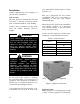
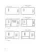
Wiring Diagrams
Unit specific wiring diagrams are laminated
and affixed inside the compressor and
control compartment door.
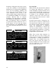
Condensate Drain Pan
Unit requires drain trap to be connected to
the condensate drain pan of the unit. Units
include one drain pan connection.
Condensate drain pipes or p-trap is factory
supplied and shipped loose in the control
compartment for field installation.
If codes require a condensate drain line, the
line should be the same pipe size or larger
than the drain connection, include a p-trap,
and pitch downward toward drain. An air
break should be used with long runs of
condensate lines.
Unit should not be operated without a
p-trap. Failure to install a p-trap may
result in overflow of condensate
water.
CAUTION