57i IP Phone Installation Guide 41-001159-00 Rev 01
Software License Agreement Aastra Telecom Inc., hereinafter known as "Seller", grants to Customer a personal, worldwide, non-transferable, non-sublicenseable and non-exclusive, restricted use license to use Software in object form solely with the Equipment for which the Software was intended. This Product may integrate programs, licensed to Aastra by third party Suppliers, for distribution under the terms of this agreement.
Table of Contents Software License Agreement..................................................................... iii Introduction .................................................................................................. 1 Phone Features ...................................................................... 1 Requirements ......................................................................... 1 About This Guide .................................................................... 1 Phone Parts ...
Introduction Congratulations on your purchase of the Model 57i IP telephone! The 57i communicates over an IP network allowing you to place and receive calls in the same manner as a regular business telephone. The 57i is capable of supporting SIP IP protocol.
Introduction SIP IP Phone Aastra 53i, 55i, 57i, 57i CT Administrator Guide – is designed for network administrators, system administrators, developers and partners who need information on installing this product on an IP network. Aastra Model 57i IP Phone User Guide – explains the most commonly used IP telephone features for an end user. These guides along with release notes, system updates, etc. can be downloaded from our Web site at www.aastratelecom.com/IPPhones.
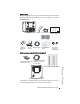
Phone Parts When you unpack your phone, you should ensure that you have all of the following items. If any part is missing, contact the supplier of your phone.
Phone Parts Warning: Do not use this PoE inline power injector to power other devices. The Model 536 Expansion Module (536EM) and Model 560 Expansion Module (560EM) attach to the right side of the 57i phone. Model 536EM provides 36 additional softkeys for the phone. Model 560EM provides 60 additional softkeys. For more information about the expansion modules, see the section, Model 536 and 560 Expansion Modules on page page 24.
Key Panel Message waiting lamp High quality speakerphone 12 softkeys - 6 static - 6 dynamic HAC handset Goodbye key Options key Hold key Redial Key Volume control Key Panel Navigational keys 11-line LCD screen Keypad Speakerphone/headset toggle key Mute key 4 call appearance lines Model 57i IP Phone Installation Guide 5
Key Descriptions Key Descriptions Keys Key Description Goodbye key - Ends an active call. The Goodbye key also exits an open list, such as the Options List, without saving changes. Options key - Accesses options to customize your phone. Your System Administrator may have already customized some of your settings. Check with your System Administrator before changing the administrator-only options. Hold key - Places an active call on hold.
Keys Key Description Navigation keys - Pressing the UP and DOWN arrow keys lets you view different status and text messages on the LCD display (if there is more than 1 line of status/text messages). These buttons also let you scroll through menu selections, such as the Options List. Pressing the LEFT and RIGHT arrow keys lets you view the different line/call appearances. While in the Options List, these keys allow you to exit or enter the current option.
Installation and Setup Installation and Setup The 57i can be setup to share a network connection with another network device. Power can be provided by an AC adapter, an 802.3af compliant network power source or with a PoE inline power injector (optional accessory). It can also be installed on a desk or mounted on the wall. If your Network Administrator has already setup your phone, please refer to the 57i User Guide (if provided) for call handling information or contact your Network Administrator.
Shared Network Connection To connect a network device (such as a computer) to the phone, connect an Ethernet cable into the network port on the top of the phone marked PC. Plug the other end of the Ethernet cable into the network port on the network device with which you are sharing the network connection.
Installation and Setup the wall.
Inline Power Not Provided If your network does not provide 802.3af compliant in-line power, you need to install the supplied AC adapter or the PoE inline power injector (optional accessory). 1. On the top of your phone, connect the Ethernet cable (provided with your phone) into the network port marked with LAN. 2. On the PoE power injector, plug the other end of the Ethernet cable into the network jack marked as indicated in the following illustration. 3.
Installation and Setup To Headset To Handset Headset (Optional) Turn the phone over and locate the headset jack marked f. Insert the headset cord into the jack until it clicks into place. Then route the headset cord through the groove as shown in the above illustration. Desk or Wall Installation Install on the Desk The desk installation for the 57i IP phone consists of two legs that attach to the back of the phone near the top corners.
For a higher viewing angle, use the second and third slots from the top. For a lower viewing angle, use the first and second slots from the top. Then push the stand towards the phone until it snaps into place. Three leg slot locations for customizing the height of the desk phone. 23.3 deg. Incline Angle 26.6 deg. Incline Angle 30.9 deg. Incline Angle Total 4 Viewing Angles Model 57i IP Phone Installation Guide 13 Installation and Setup 20.7 deg.
Installation and Setup Install on the Wall The 57i IP phone has two pre-drilled wall mounting holes on the back of the phone. Using the provided wall mount drilling template, locate and mark the position for the mounting screws on the wall. Depending on the wall type, you may need to use wall anchors. Both the screws and wall anchors are included with your phone. Place the wall mount holes on the phone over the screw heads on the wall and pull down to lock the phone in.
Customizing your Telephone There is a list of configuration options, accessed by pressing the button on the phone. You can access some of these options via the Aastra Web UI also. The following table indicates the options and the method you can use to access these options on your phone.
Customizing your Telephone Accessing Your Options via the Aastra Web UI You can use the following procedure to access the phone options using the Aastra Web UI. Aastra Web UI 1. Open your web browser and enter the phone’s IP address or host name into the address field. If the browser is using HTTP, the following redirect screen displays, followed by the “Security Alert” window. This process redirects HTTP to use HTTPS for a more secure connection.. 2. Click YES to accept the certificate 3.
The Network Status window displays for the IP phone you are accessing. 4. You can logout of the Aastra Web UI at any time by clicking Log Off. Reference For more information about changing your options using the Aastra Web UI, see the Aastra Model 57i IP Phone User Guide. Language Select a language that you would like your phone to use for displaying prompts and menus. Note: Supported languages may vary depending on configuration. Contact your Network Administrator for list of available languages.
Customizing your Telephone • Set Time This option shows the Network time, if the Time Server option is enabled. It also allows you to set the time manually. Note: if you set the time manually, the phone will not try to synchronize the time with a timeserver until the next time it is restarted. • Time Format Select a time format for how time displays on your phone (12h or 24h clock). • Set Date This option shows the Network date, if the Timeserver option is enabled.
Use the Change softkey to cycle through different backlighting options of OFF, ON, or Auto. Auto backlighting sets the phone to turn off the backlighting after a period of inactivity; the idle period is user definable under the Advanced softkey when you select the Auto option. The backlight is turned on with a key press or state change on the phone. Live Dialpad* This option turns the Live Dial Pad mode ON or OFF.
Customizing your Telephone Headset Mic Volume To adjust the headset microphone volume, press Advanced after selecting the audio option, and then select the Low, Medium, or High volume level. Call Forward Use this option to call forward your phone. Use the and buttons to move between the fields to set the call forward Number, Mode, and No. Rings. The selectable call forward mode includes: All, Busy, NoAns (No Answer), BusyNoAns (Busy No Answer), or Off; this is selected via the and buttons.
Other Phone Features Adjusting the Volume Pressing the volume button speaker, and ringer volume. adjusts the receiver, headset, • To adjust the ringer volume, leave the handset in the cradle and press the volume button while there is no active call. There are 10 settings for the ringer including Off — the display will temporarily indicate the current ringer volume setting. • To adjust the handset volume, lift the handset and press the volume button while the handset is off hook.
Other Phone Features Softkeys The 57i has 12 multi-functional softkeys: • 6 Top Keys: programmable static softkeys (up to 10 programmable functions) • 6 Bottom Keys: programmable state-based softkeys (up to 20 programmable functions) These keys are located at the center of the phone on either side of the display panel. These softkeys make call handling and call managing easier.
Using a Headset with your Telephone The 57i accepts headsets through the modular jack on the back of the phone. Contact your telephone equipment retailer or distributor to purchase a compatible headset. A non-amplified headset is required. Customers should read and observe all safety recommendations contained in headset operating guides when using any headset. Note: For best headset performance, Aastra recommends non-amplified headset equipped with modular connector.
Model 536 and 560 Expansion Modules Model 536 and 560 Expansion Modules (536EM, 560EM) The 57i IP Phone offers optional Expansion Modules that attach to the right side of the phone to provide additional softkeys. Model 536EM Model 560EM The 536EM provides 36 additional softkeys on a 57i IP Phone. The 560EM provides 60 additional softkeys. The softkeys support the following features: • BLF • Speedial • Shared Call Appearance Each key provides an LED for indicating call status.
Additional modules (up to 3 total modules) can be piggy-backed to an existing module providing an additional 108 softkeys with 536EMs and an additional 180 softkeys with 560EMs. You connect the additional modules to the right side of an existing module. The following figure illustrates the addition of multiple 536EM modules on the 57i IP Phone. Installing the 536EM or 560EM On the 536EM, there are 18 softkeys in each column (totaling 36 keys) on the keypad.
Model 536 and 560 Expansion Modules Connecting the Expansion Modules to Your Phone Use the following procedure to connect the 536EM or the 560EM to your 57i IP phone. 1. Turn your phone over to show the bottom of the phone. 2. Turn the expansion module over to show the bottom of the module. 3. Connect one end of the RJ-45 cable to the RJ-45 port on the back of your phone as indicated in the illustration below. Back of Expansion Back of Phone Module RJ-45 Connectors 4.
Troubleshooting Solutions Why is the light not coming on with a new Voice Mail Message? Your phone system or service provider must provide “Visual” Message Waiting service for this function to work. Check with your system administrator for more information. Why is my handset not working? Check to ensure that the handset cord is fully connected to both the phone and handset. See the section "Connecting a Handset or Headset" on page 11 for information.
Troubleshooting Solutions What is a softkey? The 57i has 12 softkeys (6 on the top and 6 on the bottom). You can program all 12 softkeys to perform specific functions on the phone. These keys are located at the center of the phone on either side of the display panel. See the section "Softkeys" on page 22 or refer to your Aastra Model 57i IP Phone User Guide for more information.
Limited Warranty Aastra Telecom warrants this product against defects and malfunctions during a one (1) year period from the date of original purchase. If there is a defect or malfunction, Aastra Telecom shall, at its option, and as the exclusive remedy, either repair or replace the telephone set at no charge, if returned within the warranty period. If replacement parts are used in making repairs, these parts may be refurbished, or may contain refurbished materials.
Index Numerics L 57i line settings 22 language 17 lights or LEDs MWI 21 speaker 21 status 21 locking the phone 20 A audio, setting 19 B backlight 18 C M call forward 20 call timer 21 contrast level, setting 18 message waiting, clearing 18 microphone volume, headset 20 MWI (message waiting indicator) 21 D N date network configuration settings for 20 connecting to 9 connecting to direct or shared 8 setting date 18 setting format 18 daylight savings 18 desk installation 12 dialpad, live 19 O oth
Index Index W wall installation 14 warranty, limited 29 Web UI, using 16 Index-2 Model 57i IP Phone Installation Guide
If you’ve read this owner’s manual and consulted the Troubleshooting section and still have problems, please visit our Web site at www.aastra.com, or call 1-800-574-1611 for technical assistance. © Aastra Telecom Inc.