675xi Series IP Phone 6753i - 6755i - 6757i CT www.8x8.com | 1.866.879.
Copyright 2008 8x8, Inc. www.8x8.com All Rights Reserved.
Table of Contents Virtual Office Features ............................................................................................. 1 Introduction.................................................................................................................... 2 Phone Parts Checklist ................................................................................................... 2 Phone Parts ..........................................................................................................
Table of Contents Programmable Keys................................................................................................35 Creating a Speedial Key .............................................................................................36 Line/Call Appearance Keys ........................................................................................37 Using a Headset with your Telephone .....................................................................38 Using the Telephone ............
Introduction Congratulations on the purchase of your 8x8 Virtual Office service and new telephone. The phone has been manufactured to meet very high standards for convenient and reliable service. This telephone will operate according to the preloaded scripts. Please use the interactive menu and soft buttons to access features provided by your 8x8 Virtual Office Service.
Phone Parts Phone Parts Checklist Remember to save your sales receipt in case you ever need warranty service. Check to make sure your package includes the items described below: Telephone base AC/DC adapter Telephone handset Wall mount bracket Phone line Handset cords Phone Parts When you unpack your phone, you should ensure that you have all of the following items. Remember to save your sales receipt in case you ever need warranty service.
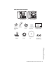
6753i and 6755i IP Phone Parts Goodbye Goodbye Line 4 Options Line 3 Hold Line 2 Holed Line 2 Redial Line 1 Redial Line 1 Options Line 3 Speaker/ Headset Speaker/ Heading Mute Mute 6753i IP Phone or 6755i IP Phone Wall Mount Drilling Template asdassa asdadsda Telephone Handset Base Desk Legs Power Adapter Handset Cord Ethernet Cable Programmable Key Card Reference CD Wall Mount Drilling Template Screws and Anchors for Wall Mounting Phone Parts Model 675xi Series IP Phone Use
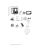
Phone Parts 6757i CT IP Phone Parts Line 4 Goodbye Wall Mount Drilling Template Line 3 Options Hold Line 2 Redial Line 1 Speaker/ Heading Mute Telephone Base Power Adapter (for 57i CT Base) Ethernet Cable asdassa asdadsda Handset Power Adapter Belt Clip (for charging cradle) Telephone Base Desk Legs Wall Mount Drilling Template Handset Cord 57i CT Cordless Handset Battery Screws and Anchors for Wall Mounting Charging Cradle for Handset Reference CD 4 — Model 675xi Series IP Phone U
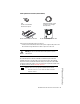
675xi Optional Accessories (Not Included) PoE (Power over Ethernet) Inline Power Injector Model 536EM Expansion Module Additional Ethernet Cable (Category 5/5e straight through cable) Model 560EM Expansion Module PoE (Power over Ethernet) Inline Power Injector • A PoE (Power over Ethernet) Inline Power Injector supplies 48v power to the 675xi Series through the Ethernet Cable on pins 4 & 5 and 7 & 8. Warning: Do not use this PoE Inline Power Injector to power other devices.
Phone Parts 6753i IP Phone Keys and Key Description K ey Panel 6 keys with LEDs (4 are programmable) High quality speakerphone HAC handset Goodbye Options Line 3 Hold Line 2 Redial Line 1 Speaker/ Heading Mute Goodbye key Options key Hold key Redial Key Volume control Navigational keys 3-line LCD screen Message waiting lamp Keypad Speakerphone/headset toggle key Mute key 3 call appearance lines 6 — Model 675xi Series IP Phone User Guide
Phone Features for the 6753i IP Phone • 3-line LCD screen • 6 top keys: 4 are programmable keys • 3 call appearance lines with LEDs • Supports up to 9 call lines • Full-duplex speakerphone for handsfree calls • Headset support (modular connector) • Built-in two-port, 10/100 Ethernet switch - lets you share a connection with your computer • Inline power support (based on 802.
Phone Parts 6755i IP Phone Keys and Key Description Key Panel 6 keys with LEDs (4 are programmable) High quality speakerphone HAC handset Goodbye Line 4 Options Line 3 Holed Line 2 Redial Line 1 Speaker/ Headset Mute Goodbye key Options key Hold key Redial Key Volume control Navigational keys 3-line LCD screen Message waiting lamp Keypad Speakerphone/headset toggle key Mute key 4 call appearance lines 8 — Model 675xi Series IP Phone User Guide
Phone Features for the 6755i IP Phone • 8 line graphical LCD screen (144 x 75 pixels) with white backlight • 12 programmable keys • 6 Top keys: Programmable hard keys (up to 6 programmable functions) • 6 Bottom keys: Programmable state-based softkeys (up to 20 programmable functions) • 4 call appearance lines with LEDs • Supports up to 9 call lines • Full-duplex speakerphone for handsfree calls • Headset support (modular connector) • Built-in-two-port, 10/100 Ethernet switch - lets you share a connection
Phone Parts 6757i CT IP Phone Keys and Key Description High quality speakphone Message waiting lamp 12 softkeys - 6 static - 6 dynamic HAC handset Goodbye key Options key] Hold key Redial Key Volume control Navigational keys 11-line LCD screen Keypad Speakerphone/headset toggle key Mute key 4 call appearance lines 10 — Model 675xi Series IP Phone User Guide
Phone Features – 6757i CT Base Unit • 11 line graphical LCD screen (144 x 128 pixels) with white backlight • 12 multi-functional softkeys • 6 Top Keys: programmable static softkeys (up to 10 programmable functions) • 6 Bottom Keys: programmable state-based softkeys (up to 20 programmable functions) • 4 call appearance lines with LEDs • Supports up to 9 call lines • Full-duplex speakerphone for handsfree calls • Headset support (modular connector) • Inline power support (based on 802.
Phone Features – 6757i CT Cordless Handset CM16E IP Phone Handset Keys and Key Description 10 1 2 3 5 4 5 11 12 6 7 13 15 14 8 15 9 16 For use with the 6757 model only Function # Function Description 1 Receiver 2 Volume key During Ringing: Adjusts ringer volume. During a call: Adjusts receiver volume. During text mode (not in a call): Moves cursor right/left. 3 Display 4 Features ƒ Key List Access key to the programmed Feature Key List. Scrolls up when in the various lists.
Function # Function Description Headset Jack 10 Status Light 11 Release Key To end calls and go on hook. Exits Menu and the various lists. 12 Menu Key Access key to the different options. scrolls down when in the various lists. Used as backspace during editing. 13 Redial Key Displays the last 10 numbers dialed.
6753i / 6755i / 6757i CT IP Phone Key Panel 6753i / 6755i / 6757i CT IP Phone Key Panel The following table identifies the keys on the key panel of your 675xi Series IP phone that you can use for handling calls. Keys Goodbye Key Description Goodbye Key - Ends an active call. The Goodbye key also exits an open list, such as the Options List, without saving changes. Options Options Key - Accesses options to customize your phone. Your System Administrator may have already customized some of your settings.
Keys Key Description Navigation Keys - Pressing the UP and DOWN arrow keys lets you view different status and text messages on the LCD display (if there is more than 1 line of status/text messages). These buttons also let you scroll through menu selections, such as the Options List. 6753i Programmable Keys - Six Top Keys: 4 are programmable keys. Note: Keys 1 and 2 are hardcoded as the SAVE and DELETE keys, respectively, and cannot be altered.
6753i / 6755i / 6757i CT IP Phone Key Panel Keys 6755i Key Description Programmable keys - 6 Top keys: programmable hard keys (up to 6 programmable functions) By default, keys 1 through 4 are assigned as Services, Directory, Callers List, and Intercom, respectively. Keys 5 and 6 have no assigned functions. All 6 keys are programmable and can be assigned to perform specific functions.
Keys 6757i CT Key Description By default, keys 1 through 4 are assigned as Services, Directory, Callers List, and Intercom, respectively: 1 - SERVICES 2 - DIRECTORY 3 - CALLERS LIST 4 - INTERCOM Accesses enhanced features and services such as XML applications and voicemail, provided by third parties. Accesses the Directory List which displays up to 200 names and phone numbers (stored in alphabetical order) Accesses the Callers List which lists the last 200 calls received.
Installation and Setup Installation and Setup The 675xi Series can be set up to share a network connection with another network device. Power can be provided by the supplied power adapter or by an 802.3af compliant network power source or with a PoE Inline Power Injector (optional accessory).
Shared Network Connection To connect a network device (such as a computer) to the phone, connect an Ethernet Cable into the network port on the top of the phone marked with PC. Plug the other end of the Ethernet cable into the network jack on the network device you are sharing the network connection with. Note: The PC jack does not supply inline power onto other network devices. All Ethernet cables used must be minimum category 5/5e straight-through cables, such as the cable provided with your phone.
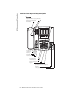
Installation and Setup Inline Power Not Provided If your network does not provide 802.3af compliant in-line power, you have to install the power adapter or the PoE inline power supply (optional accessory). 1. On the top of your phone, connect the Ethernet cable (provided with your phone) into the network port marked with LAN. 2. On the PoE power injector, plug the other end of the Ethernet cable into the network jack marked as indicated in the following illustration. 3.
Connecting a Handset or Headset Handset Turn the phone over and locate the handset jack marked . Insert one end of handset cord into the jack until it clicks into place. Then route the handset cord through the groove as shown in the illustration below. Attach the handset to the other end of the handset cord. To Headset To Handset Desk or Wall Installation The desk installation for the 675xi Series IP phone consists of two legs that attach to the back of the phone near the top corners.
Installation and Setup 3. For a lower viewing angle, use the first and second slots from the top. 4. Push the stand towards the phone until it snaps into place. Three leg slot locations for customizing the height of the desk phone. 20.7 deg. Incline Angle 23.3 deg. Incline Angle 26.6 deg. Incline Angle Total 4 Viewing Angles 22 — Model 675xi Series IP Phone User Guide 30.9 deg.
Install on the Wall The 675xi Series IP phone has two pre-drilled wall mounting holes on the back of the phone. 1. Using the provided wall mount drilling template, locate and mark the position for the mounting screws on the wall. Depending on the wall type, you may need to use wall anchors. Both the screws and wall anchors are included with your phone. 2. Place the wall mount holes on the phone over the screw heads on the wall and pull down to lock the phone in.
Installation and Setup Inserting the Key Card on your Phone This card contains the label identification spaces for (only for 6753i & 6755i) programmable keys. 1. Remove the clear plastic lens from the top front panel of the telephone by gently pressing down on the lens and sliding upward. 2. Place the card into the programmable key card slot on the top front panel of the telephone using the indentation of the plastic for alignment. 3.
There are two steps involved in setting up the 57i CT cordless handset. The charging cradle needs to be plugged in and the batteries need to be installed in the handset. Charging Cradle The charging cradle is designed to be placed on a desk or any appropriate flat surface. To set up the charging cradle: 1. Plug the modular cord of the power adapter into the jack on the bottom of the cradle. Route the cord through the retaining tabs of the molded cord slot.
Installation and Setup – 6757i CT Cordless Handset The cordless handset is automatically "factory paired" to the base station and will establish contact with the base station once both units have been successfully installed. This connection can be verified by checking for the presence of the Reception range icon m beside the battery icon b on the handset screen. Note: The battery must be charged for a minimum of six hours prior to initial usage of the handset.
Battery Status Icons The display provides “at a glance” information on the handset battery: The bars indicate the battery charge level — 4 for full, needs recharging when only 1 bar appears. The bars will flash when the battery is being recharged on the charger stand. Note: The handset is designed to recharge the batteries automatically, when required and placed on the charger stand. The battery icon will not flash and the handset does not charge every time it is placed on the stand.
Customizing your phone Access from Phone UI Phone Option Set Audio Audio Mode Headset Mic Volume Access from 8x8 Web Phone UI D D Call Forward Number Mode Number of Rings D D D Network D D D This is an Administrator option that is password protected. Phone Status Network Status Firmware Version Restart Phone D D D D D D User Password D D Phone Lock D D Accessing Your Options via the Phone UI 1. Press the Options key Options on the phone to enter the Options list. 2.
Accessing Your Options via the 8x8 Web Phone UI You can use the following procedure to access the phone options using the 8x8 Web Phone UI. 8x8 Web Phone UI 1. Open your web browser, enter the phone’s IP address or host name into the address field and press . The following logon screen displays. . The Network Status window displays for the IP phone you are accessing. Note: For a user, the default user name is “user” and the password field is left blank. .
IP Phone Features 3. You can logout of the 8x8 Web Phone UI at any time by clicking Log Off. The side menu options that display in the Network Status window are dependent on whether you log in as an Administrator or User. A longer list of options displays in the side menu for an Administrator. IP Phone Features Language Select a language that you would like your phone to use for displaying prompts and menus. Note: Supported languages may vary depending on configuration.
This option shows the Network date, if the Time server option is enabled. It also allows you to enter the date manually. Note: If you set the date manually, the phone will not synchronize the date with a time server until the next time it is restarted. • Date Format Choose from a list of formats for how the date displays on your phone. • Time Zone Choose your current time zone. Select your country by scrolling through a list, or by entering the country code (i.e.
IP Phone Features Set Audio The 675xi Series allows you to use a handset, a headset, or handsfree to handle incoming and outgoing calls. The audio mode option provides different combinations of these three methods to provide maximum flexibility in handling calls. There are four audio mode options to choose from: Audio Mode Option Description Speaker This is the default setting. Calls can be made or received using the handset or handsfree speakerphone.
There is also a system administrator level-only option to reset the phone to factory default settings. See your system administrator for details. User Password Use this option to change your user password. Valid values for entering a password are 0 to 4294967295 (integers only; symbols and alpha characters are not allowed). Default password is an empty string "" (field is blank). Phone Lock Use this option to lock the phone from unauthorized users.
6755i & 6757i CT Softkeys Status Lights (LEDs) The speaker LED, beside the key, and the Message Waiting Indicator (MWI) LED, on the top right of your phone, provide visual indications of your phone’s status. Speaker/ Headset Speaker LED Speaker LED Status Description ON solid Indicates a call is on Handsfree (speakerphone). Slow Flash Indicates you are using the headset. Rapid Flash Indicates the call is muted. Press mute.
Programmable Keys There are hard keys on the 675xi Series phone located at the top, left of the front panel display. Keys 1 and 2 (SAVE and DELTE keys) are hardcoded and cannot be changed. Keys 3-6 or 3-12 (depending on the model) are programmable keys. The following are the default functions for the programmable keys on the 675xi Series IP phone. Feature Model User Interface 6753i 6755i 6757i CT Phone Web Ring Tone & Tone Set (Refer to “Ring Tone/Tone Set” on page 31.
Programmable Keys Feature Model User Interface 6753i 6755i 6757i CT Phone Web Transfer Key (Key 5 Default) D D D D Conference Key (Key 6 Default) D D D D Intercom Key D D D None Key D D D Phone Lock Key D D D Deleting a Key D D D D Voicemail D D D D D D D D D These keys can also be set up to quickly access features such as Do Not Disturb (DND) and Voicemail. You must use the 8x8 Web Phone UI to configure the programmable keys.
3. Press (Key 1) to save the number as a speeddial key. By default, the phone automatically assigns the speeddial key to Line 1, if available. You can use the and to change the speeddial information to a different line if required. Line: 1 Change Use Save to end 4. Press (Key 1) to save the speeddial key to the line specified. Line/Call Appearance Keys The 675xi Series has between 3 and 6 (depending on the model) hard/line call appearance keys each with a corresponding status light.
Programmable Keys Using a Headset with your Telephone The 675xi Series accepts headsets through the modular jack on the back of the phone. Contact your telephone equipment retailer or distributor to purchase a compatible headset. A non-amplified headset is required. Customers should read and observe all safety recommendations contained in headset operating guides when using any headset. Note: For best headset performance, 8x8 recommends non-amplified headset equipped with modular connector.
Using the Telephone To Call an Outside Number Speaker/ Headset Pick up the phone or press . Dial 9 and then the number (7-digit if in same area code, or 9+1+area code+number). To Call Another Extension Pick up the phone or press Speaker/ Headset . Dial the extension number. Making a Call Speaker/ Headset 1. Pick up the Handset, press the button, or press the (when a headset is used), and listen for a dial tone. Speaker/ Headset button 2. Using the keypad, dial the desired telephone number.
Notes Notes 40 — Model 675xi Series IP Phone User Guide
Limited Warranty This warranty applies only to products purchased and used in the United States. What Is Covered? Any defect in materials or workmanship for one year. (See 8x8 Virtual Office terms and conditions.) Support Web/FAQs: www.8x8.com/support/faqs Email: virtualoffice@8x8.com Phone: 888-898-8733 and press option [1] for Virtual Office, then option [2] for support. Outside the U.S.
Notes
Warning! Toll fraud is committed when individuals unlawfully gain access to a customer’s telecommunication system. This is a criminal offense. Currently, we do not know of any telecommunications system that is immune to this type of criminal activity. 8x8, Inc. will not accept liability for any damages, including long distance charges, which result from unauthorized and/or unlawful use. Although 8x8, Inc.