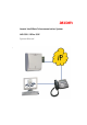
ascom Ascotel IntelliGate Telecommunication System AIP 6350 / Office 35IP System Manual a
AIP 6350 / Office 35IP Contents 1 1.1 1.2 Safety Instructions . . . . . . . . . . . . . . . . . . . . . . . . . . . . . . . . . . . . . . . . 5 About the Products. . . . . . . . . . . . . . . . . . . . . . . . . . . . . . . . . . . . . . . . . 5 Guidelines to this System Manual . . . . . . . . . . . . . . . . . . . . . . . . . . . . . . 6 2 System Description . . . . . . . . . . . . . . . . . . . . . . . . . . . . . . . . . . . . . . . 7 3 3.1 3.1.1 3.1.2 3.1.3 3.2 3.3 3.3.1 3.3.2 3.3.3 3.4 3.4.1 3.4.
AIP 6350 / Office 35IP 5 5.1 5.2 5.3 5.4 5.5 5.5.1 5.6 5.6.1 5.7 5.7.1 5.7.2 5.7.3 5.7.4 5.7.5 Expansion Card AIP 6350. . . . . . . . . . . . . . . . . . . . . . . . . . . . . . . . . . 29 AIP Card . . . . . . . . . . . . . . . . . . . . . . . . . . . . . . . . . . . . . . . . . . . . . . . . 29 DRS Module . . . . . . . . . . . . . . . . . . . . . . . . . . . . . . . . . . . . . . . . . . . . . 30 Component Placement Example . . . . . . . . . . . . . . . . . . . . . . . . . . . . . .
AIP 6350 / Office 35IP 1 Safety Instructions To exclude risk to people or goods, the following instructions must be observed. 1.1 About the Products Purpose The products AIP 6350 and Office 35IP expand the functionality of Ascotel IntelliGate and are to be used for that purpose exclusively. User group All installation and maintenance work is to be carried by authorized qualified personnel only.
AIP 6350 / Office 35IP 1.2 Guidelines to this System Manual Purpose This System Manual describes the products AIP 6350 and Office 35IP, and how to handle them. Other AIP versions are not described here. Please refer to the separate product documents. Target readership This System Manual is aimed at the persons listed under "User group" (see page 5). Conventions The abbreviation "AIP" is used throughout the text instead of the full designation "AIP 6350".
AIP 6350 / Office 35IP 2 System Description The joint use of the two IP components, namely the AIP 6350 IP interface card and the Office 35IP system terminal, makes the IP infrastructure available to telephony, and expands the Ascotel IntelliGate platform to the IP data network. The Office 35IP system terminal is a fully fledged IP terminal with the complete range of features of an Office 35.
AIP 6350 / Office 35IP This key expansion option translates into a whole range of advantages for the user: • Networked, remote workstations can be integrated at low cost into the internal telephone system, without compromising the ease with which phone calls are made. Unlike a connection via the public telephone network, no call charges are incurred and users can be reached as internal subscribers.
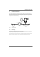
AIP 6350 / Office 35IP 3 Initial Installation This Chapter guides you through the processes used for expanding a PBX with Office 35IP terminals (referred to in the following as IP terminals). With the aid of the reference model you will be taken through the stages of planning, installation, configuration and commissioning. haz1350aaxxa0 PBX PSTN AIP 6350 IPI Router 2 LAN 2 Office 35IP Fig. 2: 3.
AIP 6350 / Office 35IP 3.1.1 Designing the System The following describes the procedure for defining the number of IP terminals you want and the AIP expansion cards required for this purpose (see "Expansion Card AIP 6350", page 29): 1. Specify the number of IP terminals. 2. Determine the number of voice channels required on the AIP based on the anticipated traffic volume.
AIP 6350 / Office 35IP Tab. 1: System design based on the example of the reference model Design Explanation PBX model Ascotel IntelliGate 2025 / 2045 / 2065 IP terminals 5 Voice channels 5 AIP Cards 1 DRS modules 1 DRS-08 3.1.2 All terminals are able to make and receive calls simultaneously max.
AIP 6350 / Office 35IP haz1352aaxxa0 PBX 500 501 PSTN AIP 6350 IPI 192.168.104.101 Router 2 LAN 2 192.168.111.200 521 192.168.111.121 Router 1 WAN LAN 1 192.168.104.200 522 511 512 513 192.168.104.111 192.168.104.112 192.168.104.113 192.168.111.122 Subnet-Mask: 255.255.255.000 Fig. 4: Call numbers and IP addresses on the reference model Tab.
AIP 6350 / Office 35IP 3.1.3 Network Planning The following describes the procedure for checking your network and planning the type of communications between AIP and the IP terminals. Note: – Please note that the expertise of an experienced network engineer is crucial for assessing and optimising the network environment. – We strongly recommend that you examine the network using a special check-list, which you can download from our support page (ascotel.ascom.ch).
AIP 6350 / Office 35IP 3.2 Installation The aim of the installation phase is to: • Fit the AIP card(s) and connect them to the network. • To connect the IP terminals to the power supply and the network. • Enter the addresses on the IP terminals. Proceed as follows: 1. Install the AIP card(s) as indicated in the instructions in the Chapter "Expansion Card AIP 6350", page 29. 2. Install the IP terminals as indicated in the Chapter "IP Terminal Office 35IP", page 20. 3.
AIP 6350 / Office 35IP 3.3.1 Adding AIP Card(s) and IP Terminals The following describes the procedure for complementing the AIMS master data with the AIP cards and IP terminals. 1. In offline mode add the required number of AIP cards (card configuration; CM_1_1_2). Make sure the slot selected in AIMS matches the slot actually used in the system.
AIP 6350 / Office 35IP 3.3.2 Configuring the Default Gateway To be able to reach IP terminals in other LAN areas, you need to enter the IP address of the router via which the LAN area of the AIP is to be exited (default gateway). This entry is superfluous if AIP and all the IP terminals are located in the same LAN area. You can define different default gateways for each individual IP terminal or for groups of IP terminals.
AIP 6350 / Office 35IP 3.3.3 AIP Configuring The following describes the procedure for configuring AIP based on the data determined during the planning phase ("Network Planning", page 13). 1. Check the settings of the general network parameters (CM_1_4_5_AIP Cards). See also Tab. 6. 2. Configure the parameters for prioritising the voice data (CM_1_4_5_AIP cards). See also Tab. 6. 3. Configure the parameters for bandwidth control (CM_1_4_5_IP Terminals and CM_1_4_5_Bandwidth Areas). See also Tab. 17. Tab.
AIP 6350 / Office 35IP 3.4.2 Functional Test For the functional test we recommend that you put the system into operation on a trial basis and check its operational suitability using a structured feedback from all users. Proceed as follows: 1. Check the following points on each IP terminal: – Do you obtain a dial tone when you pick up the handset? – Are you able to set up a connection from the terminal? – Can a connection to the terminal be set up? 2.
AIP 6350 / Office 35IP Tab. 7: Troubleshooting based on the display on the IP terminal Error indication Error "Could not register" IP connection between AIP card and IP Check AIP: • Functionality check in accordance terminal cannot be set up with chapter "Expansion Card Ethernet connection between AIP AIP 6350", page 29).
AIP 6350 / Office 35IP 4 IP Terminal Office 35IP Like any Office system terminal, the system terminal Office 35IP communicates with the PBX via the AD2 protocol. The features and user prompting are on the whole1) identical to those of the Office 35. 4.1 Expansion Options 2 expansion keypads and one alpha keyboard or 3 expansion keypads can be connected to an Office 35IP (see Operating Instructions for the Office 35IP). 4.
AIP 6350 / Office 35IP PC LAN haz1354aaxxa0 Fig. 6: Connections on the Office 35IP To install the Office 35IP proceed as follows: 1. Connect the IP terminals to the power supply. To do so, first plug the mains connector into the connection socket and only then connect the RJ45 connector to the terminal's socket. 2. Address the IP terminals in accordance with the instructions in the chapter "Configuring IP Addresses", page 22. 3. Connect the IP terminals to the network.
AIP 6350 / Office 35IP 4.3 Configuration Equipment and subscriber-specific settings can be made by the user himself via the terminal or by the system administrator via AIMS. These settings are described in the Operating Instructions for the Office 35IP. The IP addresses are entered locally on the terminal by the Installer or System Administrator. Note: The IP addresses are to be entered before the IP terminal is connected to the network.
AIP 6350 / Office 35IP 9. Select "Yes" to activate the settings. The IP terminal registers with the AIP card, providing it is already connected to the network, and the offline mode is exited. If the IP terminal is not yet connected to the network, it will register with the AIP card as soon as it is connected. Tab.
AIP 6350 / Office 35IP Proceed as follows to carry out an initialization: 1. Initiate a restart. The boot procedure is initiated. 2. Press simultaneously the key MENU and the key "0", 5 seconds after start of the boot procedure. Hold the key until the display reads "Set factory defaults". 3. Release the keys. The IP terminal is started with the initialization values. 4.
AIP 6350 / Office 35IP 4.5.2 Registering Strategies The registering process allows 2 strategies for registering IP terminals with the system: • The systematic strategy • The Plug-and-Play Strategy 4.5.2.1 Systematic Strategy The assignment of the IP address to user-network interface and phone number is determined before the installation. Use this procedure is you are planning the installation systematically: 1. Fitting and registering the AIP card. 2. Use AIMS to enter the IP address of the AIP card.
AIP 6350 / Office 35IP 4.5.2.2 The Plug-and-Play Strategy The definitive assignment of the IP address to user-network interface and phone number is determined after the installation. 1. Fitting and registering the AIP card. 2. Use AIMS to enter the IP address of the AIP card. 3. Configure the local IP addresses in the IP terminals. 4. Connect the IP terminals to the network. The IP addresses of the IP terminals are assigned one after the other to the available user-network interfaces and then registered.
AIP 6350 / Office 35IP 4.6.2 Connecting an IP Terminal Elsewhere The following describes how to change the point at which an IP terminal is connected without changing the call number, subscriber name or the terminal settings. For this the PBX does not have to be taken out of operation: If the IP addresses of the IP terminal, the default gateway and the AIP card can be taken over unchanged, proceed as follows: 1. Unplug all the connectors on the IP terminals. 2.
AIP 6350 / Office 35IP 4.6.3 Expanding the System with IP Terminals The following describes how to expand the system with additional IP terminals. For this the PBX does not have to be taken out of operation: 1. Check to make sure that none of the following limits are exceeded as a result of the expansion: – Admissible number of system terminals on the PBX (a PBX upgrade may be necessary) – Admissible number of IP terminals per AIP card (another AIP card may be necessary).
AIP 6350 / Office 35IP 5 Expansion Card AIP 6350 The extension card AIP 6350 is identically as the extension card AIP 6400, however is provided with another software. 5.1 AIP Card AIP cards are installed in an Ascotel IntelliGate 2025, 2045 or 2065. Depending on the system one or more AIP cards can be used. Tab.
AIP 6350 / Office 35IP 5.2 DRS Module DRS modules are AIP-specific modules that are fitted to the AIP card. An AIP card contains 2 slots for DRS modules. DRS modules are required for the real-time processing of voice data. Two DRS modules of different sizes are available: • The DRS-04 module is capable of processing up to 4 voice channels simultaneously • The DRS-08 module is capable of processing up to 8 voice channels simultaneously Tab.
AIP 6350 / Office 35IP 5.3 Component Placement Example An Ascotel IntelliGate 2065 is fitted with 3 AIP cards: Tab.
AIP 6350 / Office 35IP 5.4 haz0001aaxxa0 Installation of the AIP Card Warning: During the entire installation procedure, it is mandatory to observe the electrostatic discharge (ESD) precautions. The creation of an anti-static environment is highly recommended. Fitting the PBX with an AIP card: 1. Fitting an AIP card with DRS modules. 2. Disconnect the PBX from the power supply. 3.
AIP 6350 / Office 35IP 5.5 Connection on the AIP Card The AIP card is connected by a switch to the network. The PBX does not have to be switched off for this. For the connection the following cable is to be used: • Straight (1:1 through-connected) twisted-pair Ethernet cable • Category 5 or higher • With RJ-45 connectors at both ends. haz1080aaxxc0 PBX RJ45 PC RJ-45 AIP Switch PC Fig. 9: PC switch – AIP card connection Tab.
AIP 6350 / Office 35IP 5.5.1 V.24 Connection The serial interface (V.24) enables support specialists to monitor the traffic data. It has no function in normal operation. A crossed cable (null modem cable) is used to connect the PC to the AIP card via the serial interface (V.24). Tab.
AIP 6350 / Office 35IP 5.6 Commissioning the AIP Card When the PBX is switched on with a newly installed AIP card, the green system LED on the AIP card should start flashing (see Fig. 7, page 29). The network LEDs have the following functions: Tab.
AIP 6350 / Office 35IP 5.6.1 Changing the IP Address of the AIP Card via V.24 The IP and subnet address of the AIP card can be corrected without a password prompt via the V.24 access. 1. Start a hyperterminal session 2. Enter the following command line according to Tab. 16 and press "Enter": 3. Enter "reboot" and press "Enter" The card is started and the modified IP address is read in. Tab.
AIP 6350 / Office 35IP 5.7.2 Replacing an AIP Card The following describes how to replace an AIP card: 1. Use an AIMS Download to save the AIP configuration data (backup). (As this may no longer be possible if the card is defective, it is advisable to keep backups of the latest configuration on AIMS at all times.) 2. Replace the AIP card as described in the previous Chapter. 3. Start the PBX. 4. Log in with AIMS on-line on the PBX. The message "HW configuration has been changed" appears. 5.
AIP 6350 / Office 35IP 5. Use AIMS to allocate the call numbers of the IP terminals to the new port numbers (CM_1_1_3_Subscriber) so the subscriber data can be re-assigned. 6. Check the configuration using AIMS and unlock the card (CM_1_4_5_AIP Cards, Setting "AIP Card On/Off"). 7. Carry out a functional check. 5.7.4 Retrofitting an AIP card with DRS modules. An AIP card can also be retrofitted with DRS modules: 1. Disconnect the PBX from the power supply. 2.
AIP 6350 / Office 35IP 6 Network Environment This Chapter provides background information on the main network characteristics you need to take into consideration. It is assumed here that a network is already available. Please note that the expertise of an experienced network engineer is crucial for optimising the network environment. 6.
AIP 6350 / Office 35IP 6.1.1 Delay and Jitter High delay and jitter values have a considerably detrimental effect on the quality of speech. The delay values of the voice packets should be kept as small as possible. The following methods are used to reduce delay and compensate jitter: • Prioritising voice packets over other data packets: See the Chapter ("Prioritising", page 42).
AIP 6350 / Office 35IP 6.1.2 Bandwidth Management The available bandwidth can be limited, especially on WAN links. The bandwidth control of AIP 6350 prevents call connections from being set up if there is too little bandwidth available (see "Bandwidth Control", page 43). The following methods help to reduce the bandwidth requirement: • Voice compression: In the LAN area with sufficient bandwidth it makes sense to use a codec without compression (G.711) as the speech quality is better.
AIP 6350 / Office 35IP 6.2 Prioritising If the IP network is to guarantee the bandwidth required for call connections, voice packets have to be given priority compared with other data packets. The system supports the following prioritisation methods: • Expanded IP frames as per IEEE 802.1p/Q (CoS, Layer 2): AIP and IP terminals use the prioritisation field in the expanded frame header to specify the priority. Prioritisation is effected in the switches.
AIP 6350 / Office 35IP 6.3 Bandwidth Control The maximum number of call connections possible simultaneously can be limited using AIMS to ensure that the maximum number of call connections set up does not exceed the available bandwidth. The amount of bandwidth required by a call connection depends on the voice compression method. This method can be set for each individual IP terminal by selecting the correspond codec. The selected codec determines the bandwidth necessary for each call connection. Tab.
AIP 6350 / Office 35IP 6.3.1 Bandwidth Control Based on the Reference Model The following describes the procedure for defining codecs based on the example of the reference model and for setting up the bandwidth areas. An available bandwidth of 128 kbit/s is assumed as the measurement basis for the WAN link. haz1355aaxxa0 PBX 500 501 PSTN AIP 6350 IPI Router 2 LAN 2 10 Mbit/s 521 Fig.
AIP 6350 / Office 35IP 5. Specify the codec for the IP terminals in area 1. As there is sufficient bandwidth available between AIP and the IP terminals of area 1, G.711 can be used with a frame length of 10 ms. 6. Calculate how many voice channels can be open simultaneously between AIP and the IP terminals: 10 Mbit/s (LAN 1 bandwidth) 111 kbit/s (call channel with G.711 / 10 ms) = 90 voice channels In the maximum configuration with 4 fully equipped AIP cards the system supports 48 voice channels.
AIP 6350 / Office 35IP Parameters Parameter value • Voice Channels (max.) 12 Bandwidth Area 2: • Name LAN 2 • Voice Channels (max.) 4 1) Corresponds to the initialisation value Tab. 20: Number of possible call connections Call connections Channels required for each connection Channels available Possible connections Between PBX and area 1 1 12 12 Within area 1 2 12 6 Between area 1 and 2 (via WAN link) 1 4 4 Within area 2 2 4 2 6.3.
AIP 6350 / Office 35IP Tab. 21: Entering IP address ranges Subnet mask IP address Address range 255.255.255.255 xxx.xxx.xxx.xxx 1 IP address 255.255.255.0 xxx.xxx.xxx.0 xxx.xxx.xxx.1 to xxx.xxx.xxx.254 255.255.0.0 xxx.xxx.0.0 xxx.xxx.1.1 to xxx.xxx.254.254 255.0.0.0 xxx.0.0.0 xxx.1.1.1 to xxx.254.254.254 0.0.0.0 0.0.0.0 1.1.1.1 to 254.254.254.254 Tab.
AIP 6350 / Office 35IP 7 Annex 7.1 Overview of System Limits Tab. 25: System limits Number (max.) Remarks AIP Cards 1 (Ascotel IntelliGate 2025) AIP variants can be combined 2 (Ascotel IntelliGate 2045) 4 (Ascotel IntelliGate 2065) IP AD2 interfaces per card 16 Virtual interfaces without physical con8 (Ascotel IntelliGate 2025) nection. Considered as AD2 interfaces by the PBX IP terminals per interface 2 Connection MSN 1 and MSN 2 (virtual).
AIP 6350 / Office 35IP 7.3 Reference of AIMS Parameters Listed below are the parameters that can be viewed and modified using AIMS, together with a brief explanation. Tab. 27: Legend Symbols Meaning * Initialisation value (..) Display, not modifiable <..> Expected input Tab. 28: CM_1_4_5_IP Terminals Parameters Parameter values Explanation Call Number (
AIP 6350 / Office 35IP Tab. 29: CM_1_4_5_AIP Cards Parameters Parameter values Explanation Slot () Slot in which the current AIP card is located.
AIP 6350 / Office 35IP Tab. 29: CM_1_4_5_AIP Cards (continuation) Parameters Parameter values Explanation ToS Service Type 0 Normal Service 2 High Reliability 4 High Throughput *8 Low Latency Setting is valid for AIP card and its IP terminals. Dejitter Buffer Static *Dynamic Dynamic: During the connection the buffer size is continually adapted to the network conditions. Minimum size as defined by the "Buffer Size" setting. Static: Fixed buffer size as defined by the "Buffer Size" setting.
AIP 6350 / Office 35IP 7.4 Permanent Network Parameters The following parameters are set permanently and cannot be modified. Tab.
AIP 6350 / Office 35IP 7.5 Applications, Protocols and Ports The following table describes the applications, protocols and ports used by the host. Host 1 Direction Protocol Layer 4 Applications, protocols and ports used Application Tab.
AIP 6350 / Office 35IP 7.6 Software Upload This Chapter describes the software uploading procedure for AIP 6350 and Office 35IP. AIP and IP terminals implement software which has to be adapted in the course of the product's further development (application software). The latest application software can be loaded on to the terminals using the AIMS Upload Manager. 7.6.1 Upload Process The Upload process for IP terminals is described below.
AIP 6350 / Office 35IP PBX 500 [1] 501 PSTN AIMS AIP [2] [3] WAN haz1364aaxxa0 522 [4] Fig. 13: 7.6.2 Software Upload Preparing the Upload The following preparations have to be made before you start the Upload: 1. Make sure you inform all users of the time at which the upload is scheduled to be carried out as phone calls cannot be made or received while the new software is being initialised. 2. Use AIMS to make a backup of the configuration data prior to the Upload. 3.
AIP 6350 / Office 35IP 7.6.3 Uploading To load different types of application software, first load the version for the PBX software, then the one for AIP, and finally the version for the IP terminals. In each case always wait until the current Upload is fully completed before initiating a new one. Next load the IP terminals with a new application software. For this, use the PBX internal FTP server (normal case).
AIP 6350 / Office 35IP 7.6.4 Uploading via an External FTP Server The load process of the application software of the IP terminals from an external FTP server is described below. The process for loading the AIP application software follows the same pattern and is not described separately. The new software is available in the form of individual files on an external FTP server.
AIP 6350 / Office 35IP 7.6.5 Upload Termination The Upload is terminated if • .. a predefined time limit (timeout) is exceeded, • .. the FTP server cannot be accessed, • .. the power supply is interrupted. The timeout can be set separately for the IP terminals and the AIP cards in the "Options/Settings" menu in the Upload Manager. The time indication relates to the Upload process for an IP terminal or an AIP card. The upload time required depends greatly on the network's transit rate.
AIP 6350 / Office 35IP Index G G.711, G0.729 . . . . . . . . . . . . . . . . . . . . . 43 I B Initial installation . . . . . . . . . . . . . . . . . . . . .9 Initialisation values . . . . . . . . . . . . . . . . . . . 48 Installation . . . . . . . . . . . . . . . . . . . . . . . . . 14 IP Terminal Configuration . . . . . . . . . . . . . . . . . . . . 22 Configuring IP Addresses . . . . . . . . . . . 22 Connecting elsewhere . . . . . . . . . . . . . 27 Expansion options . . . . . . . . . . . . . . . .
AIP 6350 / Office 35IP S Safety instructions . . . . . . . . . . . . . . . . . . . . 5 Security . . . . . . . . . . . . . . . . . . . . . . . . . . . 41 Static routes . . . . . . . . . . . . . . . . . . . . . . . . 46 System description . . . . . . . . . . . . . . . . . . . . 7 System limits . . . . . . . . . . . . . . . . . . . . . . . 48 T ToS . . . . . . . . . . . . . . . . . . . . . . . . . . . . . . 42 Troubleshooting . . . . . . . . . . . . . . . . . . . . . 18 U Updating software . . . . . . . . .
© by ascom Order No.