6753i IP Phone Installation Guide 41-001157-06 Rev 00
Software License Agreement Aastra Telecom Inc., hereinafter known as "Seller", grants to Customer a personal, worldwide, non-transferable, non-sublicenseable and non-exclusive, restricted use license to use Software in object form solely with the Equipment for which the Software was intended. This Product may integrate programs, licensed to Aastra by third party Suppliers, for distribution under the terms of this agreement.
Table of Contents Software License Agreement.................................................................... iii Introduction ................................................................................................. 1 Phone Features ........................................................................................ Requirements ........................................................................................... About This Guide ........................................................
Introduction Congratulations on your purchase of the Model 6753i IP Phone! The 6753i communicates over an IP Network, allowing you to receive and place calls in the same manner as a regular business telephone. The 6753i is capable of supporting the SIP protocol.
Introduction About This Guide This manual describes how to physically set up your new 6753i. Not all features listed are available by default and some may depend on your phone system or service provider. Contact your system administrator if you have any questions on what features and services are available to you on your system. This guide complements the SIP IP Phone Aastra 6753i, 6755i, 6757i, 6757i CT Administrator Guide and the Aastra Model 6753i User Guide.
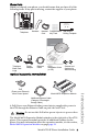
Phone Parts When you unpack your phone, you should ensure that you have all of the following items. If any part is missing, contact the supplier of your phone.
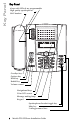
Key Panel Key Panel 6 keys with LEDs (4 are programmable High quality speakerphone HAC handset Goodbye key Options key Hold key Redial Key Volume control Navigational keys 3-line LCD screen Message waiting lamp Keypad Speakerphone/headset toggle key Mute key 3 call appearance lines 4 Model 6753i IP Phone Installation Guide
Key Description* Keys Key Description Goodbye key - Ends an active call. The Goodbye key also exits an open list, such as the Options List, without saving changes. Options key - Accesses options to customize your phone. Your System Administrator may have already customized some of your settings. Check with your System Administrator before changing the administrator-only options. Hold key - Places an active call on hold.
Key Description* Keys Key Description Navigation keys - Pressing the UP and DOWN arrow keys lets you view different status and text messages on the LCD display (if there is more than 1 line of status/text messages). These buttons also let you scroll through menu selections, such as the Options List. Pressing the LEFT and RIGHT arrow keys lets you view the different line/call appearances. While in the Options List, these keys allow you to exit or enter the current option.
Installation and Setup The 6753i can be setup to share a network connection with another network device. Power can be provided by the supplied power adapter or by an 802.3af compliant network power source or with a PoE inline power injector (optional accessory). If your System Administrator has already setup your phone, please refer to the 6753i User Guide for call handling information or contact your System Administrator.
Installation and Setup Shared Network Connection To connect a network device (such as a computer) to the phone, connect an Ethernet Cable into the network port on the top of the phone marked with PC. Plug the other end of the Ethernet cable into the network jack on the network device you are sharing the network connection with.
2. Plug the other end of the Ethernet Cable directly into the network jack on the wall.
Installation and Setup Inline Power Not Provided If your network does not provide 802.3af compliant in-line power, you have to install the power adapter or the PoE inline power supply (optional accessory). 1. On the top of your phone, connect the Ethernet cable (provided with your phone) into the network port marked with LAN. 2. On the PoE power injector, plug the other end of the Ethernet cable into the network jack marked as indicated in the following illustration. 3.
Connecting a Handset or Headset Handset Turn the phone over and locate the handset jack marked j. Insert one end of handset cord into the jack until it clicks into place. Then route the handset cord through the groove as shown in the illustration below. Attach the handset to the other end of the handset cord. To Headset To Handset Turn the phone over and locate the headset jack marked f. Insert the headset cord into the jack until it clicks into place.
Installation and Setup 4. Push the stand towards the phone until it snaps into place. Three leg slot locations for customizing the height of the desk phone. 20.7 deg. Incline Angle 23.3 deg. Incline Angle 26.6 deg. Incline Angle Total 4 Viewing Angles 12 Model 6753i IP Phone Installation Guide 30.9 deg.
Install on the Wall The 6753i IP phone has two pre-drilled wall mounting holes on the back of the phone. 1. Using the provided wall mount drilling template, locate and mark the position for the mounting screws on the wall. Depending on the wall type, you may need to use wall anchors. Both the screws and wall anchors are included with your phone. 2. Place the wall mount holes on the phone over the screw heads on the wall and pull down to lock the phone in.
Installation and Setup 5. Push the clip in until it snaps into the slot flush with the surface and only the legs on the clip are sticking up. Remove clip, turn 180 degrees, and reinsert clip. 6. Place the handset into the phone’s cradle, inserting the legs on the clip into the square hole on the handset. This allows the handset to rest in the cradle in a vertical position without slipping off when the phone is installed on the wall.
Inserting the Key Card on your Phone This card contains the label identification spaces for 6 programmable keys. 1. Remove the clear plastic lens from the top front panel of the telephone by gently pressing down on the lens and sliding upward. 2. Place the card into the programmable key card slot on the top front panel of the telephone using the indentation of the plastic for alignment. 3.
Customizing your phone Customizing your phone There is a list of configuration options, accessed by pressing the button on the phone. You can also access some of these options via the Aastra Web UI. The following table indicates the options and the method you can use to access these options on your phone.
Accessing Your Options via the Phone UI 1. Press the Options key on the phone to enter the options list. 2. To go to an Option, use and to scroll through the list, or press the number corresponding to the Option. 3. Press the Show softkey, the button, or press the digit number of the corresponding option to select an option. 4. Use the softkeys to change a selected option. 5. Press the Done softkey at any time to exit the option and save the change. 6.
Customizing your phone The Network Status window displays for the IP phone you are accessing. Note: For a user, the default user name is “user” and the password field is left blank. 3. You can logout of the Aastra Web UI at any time by clicking Log Off. The side menu options that display in the Network Status window are dependant on whether you log in as an Administrator or User. A longer list of options display in the side menu for an Administrator.
Other Phone Features Set Audio The 6753i allows you to use a handset, a headset, or handsfree to handle incoming and outgoing calls. The audio mode option provides different combinations of these three methods to provide maximum flexibility in handling calls. There are four audio mode options to choose from: Audio Mode Option Description This is the default setting. Calls can be made or received using the handset or handsfree speakerphone.
Other Phone Features • To adjust the headset volume, press the volume button while the headset is activated (activate the headset by pressing ; ensure headset audio mode is set). The headset will remain at this volume until it is adjusted again. • To adjust the speaker volume, press the volume button while the speaker is activated (activate the speaker by pressing ; ensure handsfree speakerphone audio mode is set). The speaker will remain at this volume until it is adjusted again.
Rapid Flash Indicates ringing on the line. Slow Flash Indicates a call is on hold. For more information about the Line Call Appearance keys, see the Aastra Model 6753i User Guide. Using a Headset with your Telephone The 6753i accepts headsets through the modular jack on the back of the phone. Contact your telephone equipment retailer or distributor to purchase a compatible headset. A non-amplified headset is required.
Model M670i Expansion Modules Model M670i Expansion Modules The 6753i IP Phone offers an optional Expansion Module that attaches to the right side of the phone to provide additional softkeys. The M670i provides 18 softkeys in each column (totaling 36 keys) on the keypad. Each key provides an LED for indicating call status. The M670i provides a paper label for convenient key labeling. The expansion module softkeys support all of the same key types as the phone’s softkeys and programmable keys.
Installing the Expansion Modules The M670i Expansion Module connects to the right side of a 6753i IP phone via an RJ-45 connector and a connector plate. Connector Plate RJ-45 Connector Connecting the Expansion Modules to Your Phone Use the following procedure to connect the Expansion Modules to your 6753i IP phone. 1. Turn your phone over to show the bottom of the phone. 2. Turn the expansion module over to show the bottom of the module. 3.
Model M670i Expansion Modules Connector Plate Screw Holes on Expansion Module Connector Plate Screw Holes on Phone RJ-45 Cable Back of Expansion Module Back of Phone 5. Line up the screw holes on the connector plate with the screw holes on the back of the phone. 6. Insert the two screws (included with your expansion module) into the connector plate holes and secure to the IP Phone. 7.
Attaching Multiple Expansion Modules Multiple modules (up to 3 total modules) can be piggy-backed to an IP phone providing an additional 108 softkeys with M670is. You connect the additional modules to the right side of an existing module. The following figure illustrates the addition of multiple M670i modules on the 6755i IP Phone. Model 6753i IP Phone Installation Guide 25 Model M670i Expansion Modules For more information about setting the softkeys, see the Aastra Model 6753i User Guide.
Troubleshooting Solutions Troubleshooting Solutions Why is the light not coming on with a new Voice Mail Message? Your phone system or service provider must provide “Visual” Message Waiting service for this function to work. Check with your system administrator for more information. Why is my handset not working? Check to ensure that the handset cord is fully connected to both the phone and handset. See the section "Connecting a Handset or Headset" on page 11 for information.
Limited Warranty Aastra Telecom warrants this product against defects and malfunctions during a one (1) year period from the date of original purchase. If there is a defect or malfunction, Aastra Telecom shall, at its option, and as the exclusive remedy, either repair or replace the telephone set at no charge, if returned within the warranty period. If replacement parts are used in making repairs, these parts may be refurbished, or may contain refurbished materials.
Index Numerics MWI (message waiting indicator) 20 6753i line settings 20 N C network connection, direct 7 network connection, shared 8 call timer 20 Connecting Direct Network 7 Handset or Headset 11 Shared Network 8 To Power 8 To the Network 8 customizing your phone 16 O Optional Accessories 3 P phone features 1 phone parts 3 PoE 3 power adapter 8 D R delete key 6 Requirements 1 E Ethernet Cable 8 Ethernet wall jack 7 expansion module, M670i 3, 22 expansion, module installing 23 H Handset, con
If you’ve read this owner’s manual and consulted the Troubleshooting section and still have problems, please visit our Web site at www.aastra.com, or call 1-800-574-1611 for technical assistance. © Aastra Telecom Inc.