AAVIX OUTDOORS 3000W DIGITAL INVERTER GENERATOR FOR SERVICE CALL: (USA)1-866-591-8921/(CANADA)1-514-885-0916 WARNING : To reduce the risk of injury, user must read this manual before assembling, operating and maintaining this unit, You are responsible for operating the product properly & safely. Version: V1.
WARNING! Read the following instructions before using the product! These instructions below are for your safety.PLEASE READ AND UNDERSTAND THIS MANUAL COMPLETELY BEFORE OPERATING THE MACHINE, retain them for future reference. Familiarize yourself with them to reduce hazards like personal injuries and damage to property. TABLE OF CONTENTS Safety rules.………………….…………………………………………………………………………..2 Product specifications.……….……………………………………………………………………..9 Know your generator………………………………………………………………………….
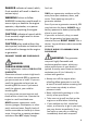
DANGER indicates a hazard, which, fresh air. WARNING Failure to follow ONLY use a generator outdoors and far away from open windows, doors, and vents. These openings can pull in generator exhaust. if not avoided, will result in death or serious injury. WARNING instructions could result in severe injury or death to the engine operator, a bystander, or a person inspecting or repairing the engine. CAUTION indicates a hazard, which, if not avoided, might result in minor or moderate injury.
water and change your clothes. When operating or transporting the machine, be sure it is kept upright. If it tilts, fuel may leak from the carburetor or fuel tank. Do not operate near open flame. Do not smoke near generator. Always operate on a firm, level surface. Do not overfill fuel tank. Gasoline may expand during operation. Do not fill to the top of the tank. Allow for expansion. Always check for spilled fuel before operating.
malfunctioning devices from generator. Do not exceed the wattage capacity of the generator by plugging in more electrical devices than the unit can handle. Do not turn on electrical devices until after they are connected to the generator. Turn off all connected electrical devices before stopping the generator. Turn the engine switch to “OFF” position when the engine is not running.
Never use it in a wet condition. Don’t spill when fueling. Never directly connect it to a house power system. Stop engine when fueling. CONNECTION TO A HOUSE POWER SUPPLY CONNECTION NOTES • Keep it at least 1m(3ft) away from inflammable. Never smoke when fueling. • Avoid connecting the generator to commercial power outlet. Avoid connecting the generator in parallel with any other generator.
power supply has failed or has been turned off for line repair. Backfeeding can electrocute or injure line maintenance personnel. Also, generator and building electrical system damage can occur when normal operating power returns if unit is used without an isolation switch.
Ground (earth) Lead Diameter: 0.12 mm (0.005 in)/ampere EX: 10 Ampere→1.2 mm (0.05 in) GENERATOR GROUND CIRCUIT In order to prevent electric shock due to shoddy electrical appliances or wrong use of electricity, the generator must be grounded with a good-quality insulated conductor. CAUTION: Make sure the control panel, louver and the inverter bottom side cooling well and without chips, mud and water come in. it may damage the engine, inverter or alternator if the cooling vent blocked.
PRODUCT SPECIFICATIONS Model Generator Engine A112004/A112005 Type Inverter Rated Frequency (Hz) 60 Rated Voltage (V) 120 Rated Output Power (KW) 2.8 Max Output Power (KW) 3.0 Power Factor 1.0 Charging Voltage (DC)(V) 12 Charging Current (DC)(A) 8 Overload Protect (DC) Non-fuse Protector USB Port 5V, 1 A&2.1A Phase Displacement (cc) Single Single cylinder, 4-stroke, forced air cooling, OHV 192 Fuel Type Unleaded Gasoline Fuel Tank Capacity Fuel Consumption (g/KW.h) 3.
KNOW YOUR GENERATOR 1 Fuel gauge 5 Air intake 2 Fuel tank cap 6 Recoil starter 3 Draw handle 7 Louver 4 Control panel 8 Muffler Accessories 1 Socket Wrench 1pc 2 Oil funnel 1pc 3 Screw driver 1pc 4 12V DC Battery charging cable 1pc 5 Spark plug wrench 1pc 6 Ignition Key 2pcs 7 RV Adapter 1pc 10
Control Panel 1 AC receptacle 8 Ground (earth) terminal 2 AC protector 9 Overload indicator LED (red) 3 DC receptacle 10 Engine switch 4 USB Port 11 Fuel cock knob 5 Low oil warning LED (yellow) 12 DC protector 6 Economy control switch 13 Choke knob 7 AC pilot LED (green) The diagrams and pictograms herewith enclosed in this manual are a guide but not necessarily an exact copy of the actual product. CONTROL FUNCTION Engine switch The engine switch controls the ignition system. 1.
Oil warning light (Yellow) When the oil level falls below the lower level, the oil warning light (yellow) comes on and then the engine stops automatically. Unless you refill with oil, the engine will not start again. NOTE: If the engine stalls or does not start, turn the engine switch to “ON” and then pull the recoil starter. If the oil warning light (yellow) flickers for a few seconds, the engine oil is insufficient. Add oil and restart.
counterclockwise. Fuel Cock Knob The fuel cock knob is used to supply fuel from the fuel tank to the carburetor. Ground (Earth) terminal Ground (Earth) terminal connects the earth line for prevention of electric shock. When the electric device is earthed, always the generator must be earthed. The generator is shipped without oil. User must add the proper amount of oil before operating the generator for the first time. The oil capacity of the engine crankcase is 0.41qts (0.45 liters).
filling will cause oil to flow into engine areas and will cause damage. Keep generator level! 7. Check for oil leaks. Tighten dipstick firmly before closing the access panel. 2. Loosen the screw and remove the small panel. Step 2-ADD GASOLINE DANGER: This generator may emit highly flammable 3. Unscrew the dipstick from the engine and set aside (Keep it clean). and explosive gasoline vapors, which can cause severe burns or even death if ignited.
fuel filter. Gasoline will expand and spill over during use when the fuel warms up even with the fuel cap in place. 4. After refueling, make sure the tank cap is tightened securely. 5. Wipe up any spilled fuel immediately with a clean, dry, soft cloth, since fuel may deteriorate painted surfaces or plastic parts. IMPORTANT: Use only unleaded gasoline. The use of leaded gasoline will cause severe damage to internal engine parts. • Never use an oil/gasoline mixture. • Never use old gasoline.
The output of the generator varies due to change temperature, altitude (lower air pressure at higher altitude) and humidity. The output of the generator is reduced when the temperature, the humidity and the altitude are higher than standard atmospheric conditions. Additionally, the load must be reduced when using in a confined areas, as generator cooling is affected. poisoning. WARNING: This generator produces powerful voltage, which can result in electrocution.
2. Check that the generator is properly grounded (Refer to “Ground the Generator”). 3. Check the oil and fuel levels. 4. Turn the ECS switch (Black) to “OFF” position. CAUTION: Take your hand off the engine switch immediately after the engine starts. If the engine fails to start, release the engine switch, wait a few seconds, then try again. Each attempt should be as short as possible as overheating and damage can occur. DO NOT crank the engine switch more than 5 seconds on any one attempt.
• In ambient temperature below 0℃(32℉ ), the engine will run at the rated speed (2800r/min) for 5 minutes to warm up the engine. • In ambient temperature below 11. Allow the generator to run for several 5℃(41℉), the engine will run at the minutes before attempting to connect speed (2800r/min) for 3 minutes to warm any electrical devices. This allows the up the engine. generator to stabilize its speed and • The ESC unit operates normally after the temperature.
NOTE: Pre-operation checks should be made each time the generator is used. The engine and muffler will be very hot after the engine has been run. Avoid touching the engine and muffler while they are still hot with any part of 3. Turn the engine switch anti-clockwise your body or clothing during inspection or to “OFF” position. repair. 4. Turn the fuel cock knob to “OFF”. WARNING: If any item in the Pre-operation check is not working properly, have it inspected and repaired before operating the generator.
1. Place the generator on a level surface. 2. Open access panel. Clean around oil fill hole. Remove dipstick and wipe the dipstick with a clean rag. Insert the dipstick into the oil fill opening without screwing in. Remove the dipstick to check the oil mark. Add recommended oil if the oil mark covers less than specified level. 3. Slowly add more oil until the oil mark reaches to the top of dipstick. Do not over fill the crankcase. 4.
grounding rod are not included in generator contents. Grounding codes can vary by location. Contact a local electrician for area codes. USING THE GENERATOR WARNING: When this generator is used on a building’s wiring system, the generator must be installed by a qualified electrician and connected to a transfer switch as a separately derived system in accordance with the National Electrical Code, NFPA 70.
the device or in its instruction manual. If this wattage cannot be found, calculate it by multiplying the Voltage requirement by the Amperage drawn: Watts = Volts x Amperes To recover the power, shut down the engine, wait until the light turns off, disconnect the plugs and restart the generator. If the inner electronic breaker does not reset, wait several minutes and try again. (The manual AC overload protector could turn off, press to reset it).
- Maximum Extension Cord Lengths by Power Requirement. If an overload occurs, shut down the generator. Unplug all electrical devices and wait five minutes. Then, start the unit back up again to get power back. APPLICATION RANGE When using the generator, make sure the total load is within rated output of a generator. Otherwise, generator damage may occur. Rated Power AC output factor power 1 ≤2,800W 0.8-0.95 ≤2,240W 0.4-0.75 (Efficiency 0.
including the lines and plug connections are in good condition before connection to the generator. Be sure any electric devices are turned off before plugging it in. Be sure the total load is within generator rated output. Be sure the receptacle load current is within receptacle rated current. 1. Wind the power lead 2 or 3 turns around handle.
require a large starting current, such as a compressor or a submergible pump. However, this is not a malfunction. The ECS switch (Black) must be turned to “OFF” to increase engine speed to rated rpm. If the generator is connected to multiple loads or electricity consumers, please remember to first connect the one with the highest starting current, and last connect the one with the lowest starting current.
CAUTION • Connect the battery charger leads to the battery terminals securely so that they are not disconnected due to engine vibration or other disturbances. 3. Make sure that the DC protector is • The DC protector turns off automatically turned on. if current above the rated flows during battery charging. Beforing restarting to charge the battery, press to resetthe DC protector. If the DC protector turns off again, stop charging the battery immediately and consult our service center. 5.
Items Frequency Pre-Op- First 8 Every Every 3 Every 6 Every As eration hours months months year 25 necescheck or 50 or 100 (daily) hours sary hours hours Engine oil Air filter Spark plug Check-level Replace Check/Clean/Replace Check/clean/Adjust gap Fuel tank & Check-refill fuel filter** Clean Fuel line Choke knob Valve clearance* * Decarboniz ation Fittings/ Fasteners Check fuel hose for crack or damage Check choke operation Check-adjust When engine is cold √ √ √ √* √ √ √* √* √ √* √ √* √ √
possible. WARNING Stop the engine before servicing. Put the engine on a level surface and remove the spark plug cap to prevent the engine from starting. Do not operate the engine in a poorly ventilated room or other enclosed area. Be sure to keep good ventilation in working area. The exhaust from the engine may contain poisonous CO, inhalation can cause shock, unconsciousness and even death. with a clean rag. Insert the dipstick into the oil fill opening without screwing in.
minutes. Prepare a used-oil pan and socket wrench in advance. 2. Then stop the engine. 3. Tilt the generator so the used-oil pan could be placed under the oil drain position and a socket wrench could be put inside to release the oil drain screw. drain. Please call a local recycling center or auto garage to arrange oil disposal. Step 2 refill engine oil CAUTION Do not tilt the generator when adding engine oil.
2. Remove spark plug boot. Be careful not to tear insulation or wire. 3. Unscrew the spark plug counterclockwise from the engine by the spark plug wrench provided. There is limited space for the wrench to turn. Use both rows of holes in the spark plug wrench to gain leverage to loosen the plug. 4. Visually inspect the spark plug for cracks or excessive electrode wear. Replace as necessary.Remove the carbon.
CARBURETOR ADJUSTMENT WARNING The carburetor is a vital part of the engine. Adjusting should be left to our company authorized dealer with the professional knowledge, specialized date, and equipment to do so properly. AIR FILTER Routine maintenance of the air cleaner helps maintain proper airflow to the carburetor. Occasionally check that the air cleaner is free of excessive dirt. Refer to Recommended Maintenance Schedule above.
4) tighten all screws well CAUTION: Be sure the foam element sealing surface to match the air filter case, so there is no air leak. The engine should never run without the element; excessive piston and cylinder wear may result. Never use solvent while smoking or in the vicinity of an open flame. Running the engine with dirty, 8. Reinstall the air filter element, replace the air filter cover in its original position. 9. Reinstall the access panel and tighten the screw.
5. Check the muffler screen and spark arrester. Replace them if damaged. 2. Loosen the bolt ③ and then remove the muffler cap ④, the muffler screen⑤. 6. Reinstall the spark arrester and muffler screen and the muffler cap. 7. Reinstall the cover and tighten the screws. FUEL TANK FILTER WARNING Never use the gasoline while smoking or in the vicinity of an open flame. 3. Use a flathead screw driver to pry the spark arrester out from the muffler. Remove the spark arrester. 1.
BATTERY This generator is equipped with a sealed-type (MF) battery, which does not require any maintenance. There is no need to check the electrolyte or to add distilled water. This product is equipped with an automatic battery charging circuit. The battery will receive charging voltage when the engine is running. The battery will maintain a proper charge if the unit is used on a regular basis (about once every two weeks).
panel, but donot tighten it fully. CAUTION Immediately wipe off spilled fuel with a clean, dry, soft cloth, since fuel may deteriorate painted surfaces or plastic parts. 5. Remove the six screws, and then remove the access panel ②. 4) tighten all screws well 11. Start generator without any device connected to it until it stops. This burns out the any fuel in the carburetor. 6. Insert the fuel drain hose of the carburettor into the fuel container. 7.
Clamp the red wire to the positive (+) terminal and the black wire to the negative (-) terminal of the battery. Do not reverse these positions. Be sure the battery is installed on the battery box. 2. Disconnect the negative lead (-/BLACK) first, then the positive lead (+/RED) from the battery. 3. Store the battery in a cool, dark and dry place and charge it once a month. Do not store the battery in an excessively warm or cold place [i.e., less than 0°C (30°F) or more than 30°C (90°F)]. WARNING: 1.
once half one year. Keep the generator upright. Never CAUTION: Never place any type of storage cover on the generator while it is still hot. TRANSPORTATION place the generator side down. Doing so will make it difficult to start. Tighten fuel cap. Drain the fuel tank if possible (see “Drain the Fuel Tank”). TROUBLESHOOTING IMPORTANT: If trouble persists, please call our customer service center.
Engine stops 1.No fuel in tank 2.Clogged fuel line 3.Clogged carburetor Refuel Clean fuel line Clean carburetor 4. Air filter is dirty. Clean or replace air filter. 5.Faulty ignition system Consult service center Not enough oil in crankcase Add or change oil Engine is out of fuel Add fuel. Blue smoke Generator inclined, oil Move generator to a level position in exhaust entered combustion Too much oil was added to Drain excessive oil. the crankcase. Generator Bad connecting wires/cables.
WIRING DIAGRAM 39
A112004 EXPLODED VIEW AND PART LIST FIG.
FIG.
FIG.
3-21 Bushing 4 A112004-3-21 3-22 Long Handel 1 A112004-3-22 3-23 Short Handel 1 A112004-3-23 3-24 Left Panel 1 A112004-3-24 3-25 Tank Support Base 2 A112004-3-25 3-26 Rear Panel 1 A112004-3-26 3-27 Oil Panel 1 A112004-3-27 3-28 Front Panel 1 A112004-3-28 3-29 Push Handel Part 1 A112004-3-29 3-30 Push Handel Box 1 A112004-3-30 3-31 Right Panel 1 A112004-3-31 3-32 Top Cover 1 A112004-3-32 3-33 Tank Mouth Rubber 1 A112004-3-33 3-34 Mirror 1 A112004-3-34 F
4-9 11# Rubber Parts 4 A112004-4-9 4-10 Bushing Φ9.1XΦ7X7.1 4 A112004-4-10 4-11 Shim Φ18XΦ6.5X1 4 A112004-4-11 4-12 Flange Bolt M6x12 4 A112004-4-12 4-13 Cross Screw M4X14 2 A112004-4-13 FIG.
A112005 EXPLODED VIEW AND PART LIST FIG.
FIG.
FIG.
3-21 Bushing 4 A112005-3-21 3-22 Long Handel 1 A112005-3-22 3-23 Short Handel 1 A112005-3-23 3-24 Left Panel 1 A112005-3-24 3-25 Tank Support Base 2 A112005-3-25 3-26 Rear Panel 1 A112005-3-26 3-27 Oil Panel 1 A112005-3-27 3-28 Front Panel 1 A112005-3-28 3-29 Push Handel Part 1 A112005-3-29 3-30 Push Handel Box 1 A112005-3-30 3-31 Right Panel 1 A112005-3-31 3-32 Top Cover 1 A112005-3-32 3-33 Tank Mouth Rubber 1 A112005-3-33 3-34 Mirror 1 A112005-3-34 F
4-9 11# Rubber Parts 4 A112005-4-9 4-10 Bushing Φ9.1XΦ7X7.1 4 A112005-4-10 4-11 Shim Φ18XΦ6.5X1 4 A112005-4-11 4-12 Flange Bolt M6x12 4 A112005-4-12 4-13 Cross Screw M4X14 2 A112005-4-13 FIG.