Snow Thrower WR67442D Barcode: WARNING! Read the instructions before using the product!
Let’s get started… These instructions are for your safety. Please read through them thoroughly before use and retain them for future reference. Getting started Your product ........................................................................................................ 3 Technical and legal information ........................................................................... 7 Before you start..................................................................................................
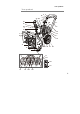
Your product Your product 25 4 27 27a 8a 2 5 3 24 22 26 8c 1 8d 6 8 8e 23 9 21 9a 7 19 11 14 15 16 10 17 18 13 11 11a 11b 11c 12 11f 11d 11e 3
RUS 35 20 30 32 33 34 36 4 37
39 38 40 41 5
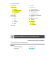
1. Handle a. Auger shaft 2. Drive control lever b. Shear pin (x 4) 3. Gear lever c. Nut (x 4) 4. Auger control lever d. Grease adding bolt 5. Cross plate e. Oil drain bolt a. Nut* 6. Auger wire f. Gear box 12. Scraper a. Sleeve* a. Bolt* b. Connection plate* b. Washer* c. c. Nut* Location pin* d. S-pin* 13. Skid shoe 7. Cylinder fins a. Bolt* 8. Discharge chute b. Washer* a. Deflector guard c. Nut* b. Bolt* (x 2) 14. Belt case c. Knob (x 2) 15. Oil tank cap d. Fence a.
23. Upper handle bar 24. Gear wire 32. Choke 25. Drive wire 33. Fuel lever a. Sleeve* 34. Fuel drain screw b. Connection plate* 35. Spark plug connector c. Location pin* 36. Hex key (5 mm) d. S-pin* 37. Assembly wrench 26. Silencer 38. Screwdriver (crosshead & slotted) 27. Fuel tank 39. Spark plug wrench a. Cap 40. Tool bag b. Filter* 41. Oil funnel c. Tongue* d. Slot* a. Cap* b. Adapter* 30. Primer NOTE: Parts marked with * are not shown in this overview.
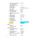
> Specific fuel consumption at max. engine power 395 g/kWh > Fuel consumption at max. engine power 1.7 kg/h > Oil tank capacity 0.6 l (600 cm³) > Engine oil type 4-stroke engine oil / 5W-30 > Engine type G210FDS > Engine displacement 212 cm³ > Max. engine speed 3600 min-1 > Max. shaft brake power of the engine 4.4 kW > Spark plug type Torch F7RTC > Spark plug gap 0.6 – 0.
> Uncertainty K 1.5 m/s² The sound values have been determined according to noise test code given in EN ISO 3744 and ISO 11094. The sound intensity level for the operator may exceed 80 dB(A) and ear protection measures are necessary. The declared vibration value has been measured in accordance with a standard test method (according to EN ISO 20643) and may be used for comparing one product with another. The declared vibration value may also be used in a preliminary assessment of exposure.
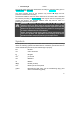
Lock / to tighten or secure Unlock / to loosen Note / Remark Caution / Warning. Read the instruction manual. Wear hearing protection. Wear eye protection. Wear respiratory protection. Wear protective gloves. Wear tight-fitted protective clothes. Wear protective, slip-resistant footwear.
Risk of fire / flammable materials Hot surface, do not touch. High temperatures on the product’s surfaces and structural parts that could cause burns, if they are touched. The product can also stay hot for a longer period of time after operation! Objects thrown by the product could hit the user or other bystanders. Always ensure that other people and pets remain at a safe distance from the product when it is in operation. In general, children must not come near the area where the product is.
Do not open or remove safety shields while engine is running. Warning! Rotating working tool, keep hands away! Do not insert your hands into the discharge chute. Stop the engine before unclogging discharge chute. Do not operate on steep slopes! Only refuel unleaded petrol! Add engine oil Check and refill oil. Switch the engine off while you are refilling the tanks! Fuel lever: move right to open, move left to close.
Choke: move left to close, move right to open Choke – CLOSE position Choke – OPEN position Maximum speed Minimum speed Primer Engine manual start; Recoil starter Drive control Auger control 13
Discharge Chute – Height Adjustment: Up Discharge Chute – Height Adjustment: Down Discharge Chute – Rotate left Discharge Chute – Rotate right Safety warnings 1. This product is not intended for use by persons (including children) with reduced physical, sensory or mental capabilities, or lack of experience and knowledge, unless they have been given supervision or instruction concerning use of the product by a person responsible for their safety. 2.
3. Keep the area of operation clear of all persons, particularly small children, and pets. 4. Exercise caution to avoid slipping or falling, especially when operating in reverse. Preparation 1. Thoroughly inspect the area where the product is to be used and remove all doormats, sleds, boards, wires, and other foreign objects. 2. Disengage all clutches and shift into neutral before starting the engine. 3. Do not operate the product without wearing adequate winter garments.
3. After striking a foreign object, stop the engine, remove the wire from the sparkplug, thoroughly inspect the product for any damage, and repair the damage before restarting and operating the product. 4. If the product should start to vibrate abnormally, stop the engine and check immediately for the cause. Vibration is generally a warning of trouble. 5.
19. Take all possible precautions when leaving the product unattended. Disengage the power take-off, lower the attachments, shift into neutral, set the parking brake, stop the engine and remove the key. Maintenance and storage 1. Check shear bolts; engine-mounted bolt, etc., at frequent intervals for proper tightness to be sure the product is in safe working condition. 2.
4. Make sure that air circulation is adequate and good. The product must be easily accessible from all sides. 5. Always switch the product off and let it cool down, before refuelling it. Petrol is highly flammable. Never smoke when you are refuelling the product. Do not refuel the product, if there is an open fire in the vicinity! 6. Always use suitable aids such as funnels and filler necks. Do not spill any fuel on the product or its exhaust system. There is a risk of ignition.
3. Use correct accessories for the product and ensure they in good condition. 4. Keep tight grip on the handles/grip surface. 5. Maintain this product in accordance with these instructions and keep it well lubricated (where appropriate). 6. Plan your work schedule to spread any high vibration tool use a longer period of time. Emergency Familiarise yourself with the use of this product by means of this instruction manual. Memorise the safety directions and follow them to the letter.
4. Burns, if touching hot surfaces.
Before you start Unpacking NOTE: The product is heavy, ask another person for assistance if required. 1. Unpack all parts and lay them on a flat, stable surface. 2. Remove all packing materials and shipping devices if applicable. 3. Make sure the delivery contents are complete and free of any damage. If you find that parts are missing or show damage do not use the product but contact your dealer. Using an incomplete or damaged product represents a hazard to people and property. 4.
Assembly WARNING! The product must be fully assembled before operation! Do not use a product that is only partly assembled or assembled with damaged parts! Follow the assembly instructions step-by-step and use the pictures provided as a visual guide to easily assemble the product Disconnect the spark plug connector (35) from the spark plug! NOTE: Take care of small parts that are removed during assembly or when making adjustments. Keep them secure to avoid loss.
Fig. 2 4. Align the holes on the upper handle bar (23) with those on the lower handle bar (19). 5. Secure the connection with the knobs (21a), bolts (21c), washers (21b) and nuts (21d) (Fig. 3). Pay attention to correct order. Fig.
7. Ensure the auger wire (6) and drive wire (25) are well connected with auger control lever (4) and drive control lever (2) (Fig. 5). 2 25 4 6 Fig.
NOTE: Be careful not to damage/deform the fence (8d) when assemble the discharge chute (8). 1. Remove the pre-assembled bolts (8f) and nuts (8g) from the chute seat (8e) (Fig. 13). Fig. 13 2. Place the discharge chute (8) onto the chute seat (8e). Adjust the mitre angle of the chute clockwise or anticlockwise to align the holes with those on the chute seat (8e). 3.
8 8d 8f 8e 8g 37 Fig.
30
1. Pull the handle (9b) of the shovel (9) to remove it from both hooks (9a) (Fig. 17). Fig. 17 2. Clamp the side with the blade (9c) onto the hook (9a) and then the handle (9b) to the second hook (Fig. 18). Fig. 18 Use the shovel (9) to clear up the snow inside the guard (10) and discharge chute (8) (Fig. 19). NOTE: Be careful not to damage/deform the fence (8d) when clearing up snow from the discharge chute (8). Fig.
Fuel and engine oil This product is equipped with a 4-stroke engine. Before operation you have to add proper fuel and engine oil. 1. Place the product on a stable, level surface. We recommend laying a nonflammable sheet underneath. 2. Use proper funnels. Avoid splitting and overfilling the tanks. WARNING! Ensure that there are no naked flames around the product! Do not smoke while filling fuel and oil! 3. Always dispose fuel, used oil and objects contaminated with them in accordance with local regulations.
27a 27c 27d Fig. 20 27b FUEL LEVEL max. marking Fig. 21 NOTE: Fuel deteriorates over time. It may be difficult to start the engine if you use fuel which has been kept for more than 30 days. Towards the end of the season, it is advisable to put only as much fuel in the tank as you need for each use, since it should be completely used up before storing the product. Empty remaining fuel from the tank when storing the product for over 30 days. 5. Wipe any spilled fuel with a soft cloth if necessary 6.
WARNING! This product is not supplied with oil. However, for manufacturing reasons it is possible that a small quantity may be in the engine! Before operating this product it is essential to fill it with proper oil (see ”Technical specifications”)! 1. Unscrew and remove the oil tank cap (15) (Fig. 22). NOTE: The engine unit of this product is equipped with two oil tank caps and drain screws on the left and right side. To fill with oil or remove you can choose either side. Fig. 22 2.
Fig. 23 3. Gradually add good-quality engine oil 5W-30. Allow the oil to settle. 4. Check the oil level frequently while filling. Wipe the oil dipstick clean; refit and tighten the oil tank cap (15) and then remove it again. The oil level must be between the “H (High)” and “L (Low)” markings. Add more oil if necessary. Do not overfill (Fig. 24). Fig. 24 5. Wipe spilled oil with a soft cloth and screw the oil tank cap (15).
Quick start Operating controls Drive control Auger control 28a Ignition switch on/off 34 Gear lever Deflector guard Recoil starter handle Snow breaker Wheel Auger 36 Skid shoes
Set up Assemble Adjust Add petrol Add engine oil Cold Start Set fuel lever to the right (OPEN) Set choke to the left (CLOSE) Set throttle lever to left (TORTOISE) Set ignition switch to “ON” Press primer 3 times Pull recoil starter handle Run idle for 20-30 seconds Move gradually the choke to the right (OPEN) Set throttle lever between TORTOISE and HARE Operate 37
Warm Start Set fuel lever to right (OPEN) Set choke to the right (OPEN) Set throttle lever to left (TORTOI SE) Run idle for 20-30 seconds Set throttle lever between TORTOISE and HARE Operate Set ignition switch to “ON” Stopping Release auger lever and drive lever Storage 38 Set throttle lever to left (TORTOIS E) Run idle for 20-30 seconds Set ignition switch to “OFF Pull recoil starter handle
Empty fuel tank Remove oil Clean and maintain Store WARNING! This quick start provides only a short overview of how to start and stop the product! For safe use it is essential to read the entire instruction manual before first use! 39
In more detail… Product functions................................................................. xx Operation............................................................................. xx Care and maintenance ........................................................ xx Troubleshooting................................................................... xx Recycling and disposal........................................................ xx Guarantee.............................................................
Product functions Intended use This petrol snow thrower MSTP196 is designated with a maximum power output of 4.1 kW. This product is intended for clearing garden paths, yards and private approach lanes from snow in domestic areas. The product may not be used on high plateaus like roof gardens. For safety reasons it is essential to read the entire instruction manual before first operation and to observe all the instructions therein.
Fig. 25 2. Raise or lower the deflector guard (8a) to the desired height (Figs. 26, 27). Fig. 26 Chute deflector in lower position 3. 42 Fig. 27 Chute deflector in upper position Keep the bolts (8b) in position with the hex key (36) and retighten the knobs (8c).
4. The discharge chute (8) can be adjusted approx. 180 degrees by rotating the crank (28). Rotate the crank (28) clockwise to turn the discharge chute (8) to the left; anticlockwise to turn the chute (8) to the right (Figs. 28, 29). Fig. 28 Turn left Fig. 29 Turn right Auger control lever The auger control lever (4) is located on upper side of the left handle (1). Squeeze the lever to engage the auger. Release the lever to stop the snow throwing action (Fig. 30).
NOTE: Perform the following test before operating your product for the first time and the start of each winter season. When the auger control lever (4) is released and in the disengaged upper position, the auger wire should have very little slack. It should not be tight. 1. Stand behind the product. 2. Engage the auger and allow the auger (11) to remain engaged for approx. 10 seconds. 3. Release the auger control lever (4). 4. Repeat the step 2, 3 and 4 for several times. 5.
Gear lever The gear lever (3) is located in the crossbar between the handles (1) and is used to determine both ground speed and direction. It can be moved to any of 8 positions (6 forward speeds, 2 reverse speeds).
Reverse speeds Press the gear lever (3) downwards and set it to one of the two positions to the right to operate the product in reverse mode (R1 = slow, R2 = fast) (Fig. 33). Fig. 33 WARNING! Be extremely careful when moving backwards! Pay attention to your steps! Ensure that you do not step on obstacles! Primer 1. Use the primer (30) when starting the product with a cold engine (Fig. 34). 30 Fig.
Recoil starter 1. The recoil starter handle (22) is positioned at the back side of the engine unit. 2. Pull on the recoil starter handle (22) to start the engine (Fig. 35). Fig.
Choke 1. Move the choke (32) to “CLOSE” position for cold start (Fig. 38). 2. Move the choke (32) to “OPEN” position for warm start and normal use (Fig. 39). 32 Fig. 38 Fig. 39 Fuel lever 1. Move the fuel lever (33) to “ON” position for opening fuel channel (Fig. 40). 2. Move the fuel lever (33) to “OFF” position for shutting off fuel channel (Fig. 41).
33 Fig. 41, “OFF” position Fig. 40, “ON” position Ignition switch 1. Set the ignition switch (20) to “ON” position to start the product (Fig. 42). 2. Set the ignition switch (20) to “OFF” position to shut off the product (Fig. 43). 20 Fig. 42, “ON” position Fig. 43, “OFF” position Carburettor If the auger fails to operate at operational speed the carburettor may need to be adjusted. Please contact an authorised service centre or similar qualified specialist.
2. Fix the skid shoes (13) in an lower or middle position for close snow removal on a smooth surface. 3. Fix the skid shoes (13) in a upper position when the area to be cleared is uneven (Fig. 44). NOTE: Always adjust both skid shoes (13) in the same position! Fig.
Operation General operation 1. Check the product as well as accessories for damage before each use. Do not use the product if it is damaged or shows wear. 2. Double check that accessories are properly fixed. 3. Check the fuel and engine oil level, refill if necessary. 4. Push the product forward by while squeezing the levers on the handles. Keep the levers and handles dry and clean to ensure safe support. 5. Ensure that the air vents are always unobstructed and clear.
1. Move the fuel lever (33) to the right (ON position). 2. Move the choke (32) to the left (CLOSE position) (Fig. 45). 33 30 32 Fig. 45 3. Set ignition switch (20) to “ON” position (Fig. 46). 20 Fig. 46 4. Press the primer (30) 3-5 times if the engine is cold (low environment temperature -20°C).
5. Pull the recoil starter handle (22) slowly until you feel a definite resistance (starter engaged) and then pull firmly to start the engine. WARNING! Allow the cable to return slowly and in a controlled manner each time it is pulled! 6. Let the engine run in idle for about 20-30 seconds to warm it up. 7. Gradually move the choke (32) to the right (OPEN position) as the engine warms up. NOTE: When moving the choke to the right (OPEN position) and the engine speed gets inconsistent.
33 30 32 Fig. 47 4. Set ignition switch (20) to “ON” position (Fig. 48). 20 Fig. 48 5. Do not press the primer (30) if the engine is warm. 6. Pull the recoil starter handle (22) slowly until you feel a definite resistance (starter engaged) and then pull firmly to start the engine.
7. Squeeze the auger control lever (4) to clear snow. 8. Squeeze the drive control lever (2) to move the product. Stopping 1. Release the auger control lever (4) and drive control lever (2). 2. Let the product run idle for about 20-30 seconds and then set ignition switch (20) to position “OFF” (Fig. 49). 35 20 32 Fig. 49 28c 28b 28a 3. Move the fuel34 lever (33) to the left (OFF position). 4. Leave the choke (32) in its opened position (Fig. 50).
32 33 Fig. 50 NOTE: The auger (11) will continue to rotate for a short period after the product has been switched off. Clearing snow WARNING! Foreign objects, such as rocks, broken glass, nails, , wire, or string, can be picked up and thrown by the product, causing damage and serious personal injury! Ensure that no hidden objects are covered by the snow! Remove all foreign objects from the area to be cleared before operating the product! 1.
3. Pay attention to the wind direction. If possible, move in the same direction as the wind so that the snow is not thrown against the wind (and thus back into your face and on the just cleared path). 4. Do not push the product with excessive force. You should push the product gently and evenly in accordance with the products throw rate. 5. Some parts of the product may freeze under extreme temperature conditions. Do not attempt to operate the product with frozen parts.
Care and maintenance The golden rules for care WARNING! Always switch the product off, disconnect the spark plug connector and let the product cool down before performing inspection, maintenance and cleaning work! 1. Keep the product clean. Remove debris from it after each use and before storage. 2. Regular and proper cleaning will help ensure safe use and prolong the life of the product. 3. Inspect the product before each use for worn and damaged parts.
Maintenance Table Part To do Before/after each use 5 hours Engine Oil Check x Engine Oil Change Spark plug Check Spark plug Clean Spark plug Replace whenever necessary Valve play Adjust whenever necessary Exhaust area Clean x 25 hours 50 hours / half year 100 hours / once a year x x x Spare parts/Replacement parts The following parts of this product may be replaced by the consumer. Spare parts are available at an authorized dealer or through our customer service.
Removing blockages WARNING! Wear protective gloves when removing blockages! Use proper tools to remove debris, e. g. a wooden stick! Never use your bare hands! Warning! Rotating working tool, keep hands away! Do not insert your hands into the discharge chute. 1. Check the discharge chute (8) for blockages and use the shovel (9) to remove any. 2. Check the auger (11) and remove possible clogging with the shovel (9), brush or blunt tool. Check to make sure the auger is in an undamaged condition.
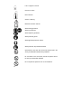
Remove the shear pins (11b) and nuts (11c) on the auger shaft (11a). Spray lubricant inside the shaft and lubricate the auger bearings at least once a season (Fig. 51). 1. Unscrew the oil drain bolt (11e) underneath the gear box (11f). 2. Add freezing lubricating grease through opening of the grease adding bolt (11d) with an oil gun (not provided). 3. When the grease comes out of the place of oil drain hole underneath the gear box (11f), clean and dry the place and tighten the oil drain bolt (11e). 4.
3. Secure the skid shoes (13) with the bolts (13a), washers (13b) and nuts (13c) in reverse order (Fig. 52). 13a 10 Fig. 52 13b 13c 13 Scraper 1. The scraper (12) is located at the base of the product beneath the guard (10). 2. Detach and remove the worn scraper (12) from the product by removing the bolts (12a), washers (12b) and nuts (13c) that hold it in place (Fig. 53). 12 10 Fig. 53 3.
washers (12b) and nuts (12c) in reverse order (Fig. 54). Fig. 54 Belt 1. Loosen the bolts (A) on both sides of the belt case (14) and remove them together with the case (Fig. 55). 14 Fig. 55 A 2. Check the belts for any damage and wear. Have them replaced if they are damaged or worn. Otherwise the performance and safety of the product cannot be guaranteed. 3. Attach and secure the belt case (14) with the bolts. Shear pin A clog or jam in the auger may cause one or both of the shear pins to break.
1. Unscrew the nut (11c) from the broken shear pin (11b) and remove them from the auger shaft (11a). 2. Place a new shear pin (11b) through the hole in the auger shaft (11a) and tighten it with the nut (11c) (Fig. 56). 11b 11a 11c Fig. 56 Wheels 1. Check the wheels (17) for pressure before every operation. Pump up the wheels with a proper tyre pump if necessary. Observe the max. allowed pressure marked on the wheels. 2. If the wheels (17) are damaged or worn replace them with a new one of the same type.
Check 1. Unscrew the oil tank cap (15). 2. Wipe the oil dipstick clean; refit and tighten the filler cap and then remove it again. The oil level must be between the “H” and “L” markings. 3. Refill if the oil level is too low. 4. Drain oil if the oil level is too high. 5. The oil should be clear and thick. If the oil is sticky or contains dirt particles the oil must be changed. Change 1. Place a suitable container under oil drain screw (16) to collect drained oil. 2.
Fuel NOTE: Petrol deteriorates over time. Engine starting may be difficult if you use petrol kept for more than 30 days. Do not reuse any fuel that has been removed. Always empty the fuel tank when storing over 30 days. 1. Empty the fuel tank (27) when storing the product over 30 days to avoid deterioration of the fuel. 2. Place a suitable container under fuel drain screw (34) to collect drained fuel 3.
3. Loosen the spark plug with the spark plug wrench (39) and carefully remove it (Fig. 60). 35 39 Fig. 59 Fig. 60 4. The colour of the electrode should be light-brown coloured. 5. Remove debris from the electrode with a soft wired brush; avoid heavy cleaning of the electrode. 6. Dry the spark plug with a soft cloth if it is wet from petrol. 7. Check the spark plug gap. It should be 0.6 – 0.7 mm (Fig. 61). Fig. 61 8.
9. When replacing the spark plug, first screw it in hand tight and then lightly tighten it with the spark plug wrench. WARNING! Do not over tighten the spark plug to avoid any damage! Wire adjustment Contact an authorised service centre or similar qualified specialist if the drive (25) and/or auger wire (6) need to be readjusted. Carburettor The carburettor is pre-adjusted by the manufacturer.
Storage 1. Clean the product as described above. 2. Store the product and its accessories in a dry, frost-free place. 3. Always store the product in a place that is inaccessible to children. The ideal storage temperature is between 10 and 30°C. 4. We recommend using the original package for storage or covering the product with a suitable cloth or enclosure to protect it against dust. 5.
Problem 1. Engine does not start 2. Engine stops 3. Unsatisfactory result Possible cause 1.1. Not enough fuel in fuel tank 1.2. Primer has not been pressed at cold start 1.3. Primer has been pressed at warm start 1.4. Spark plug is wet 1.5. Spark plug is damaged 2.1. Not enough fuel in fuel tank 2.2. Auger is blocked 3.1. Auger damaged, worn or bent 3.2. Impeller blocked 3.3. Auger/chute blocked 4. Excessive vibration/noise or exhaust 3.4. Shear pin broken 4.1. Auger is damaged 4.2. Auger is blocked 4.
3. The product comes in a package that protects it against damages during shipping. Keep the package until you are sure that all parts have been delivered and the product is function properly. Recycle the package afterwards. Guarantee Guarantee (for UK only) 1. This product has been manufactured to a high quality standard. It is guaranteed against faulty materials and workmanship for 24 months from purchase, please retain your till receipt as proof of purchase. 2.