
User manual


Publication 1763-UM001E-EN-P - March 2015
46 Wiring Your Controller
Grounding the Controller
In solid-state control systems, grounding and wire routing helps limit the
effects of noise due to electromagnetic interference (EMI). Run the ground
connection from the ground screw of the controller to the ground bus prior to
connecting any devices. Use AWG #14 wire. For AC-powered controllers, this
connection must be made for safety purposes.
This product is intended to be mounted to a well grounded mounting surface
such as a metal panel. Refer to the Industrial Automation Wiring and Grounding
Guidelines, publication 1770-4.1, for additional information. Additional
grounding connections from the mounting tab or DIN rail, if used, are not
required unless the mounting surface cannot be grounded.
ATTENTION
All devices connected to the RS-232/485 communication port must be referenced to
controller ground, or be floating (not referenced to a potential other than ground).
Failure to follow this procedure may result in property damage or personal injury.
• For 1763-L16BWA controllers, the COM of the sensor supply is also connected to
chassis ground internally. The 24V DC sensor power source should not be used to power
output circuits. It should only be used to power input devices.
• For 1763-L16BBB and 1763-L16DWD controllers, the VDC NEUT or common terminal
of the power supply is also connected to chassis ground internally.
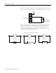
TIP
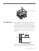
Use all four mounting positions for panel mounting
installation.
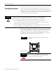
ATTENTION
Remove the protective debris strip before applying
power to the controller. Failure to remove the strip
may cause the controller to overheat.
ESC OK
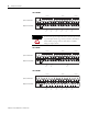
Grounding stamping