
User manual


Publication 1763-UM001E-EN-P - March 2015
Wiring Your Controller 47
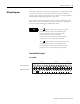
Wiring Diagrams
The following illustrations show the wiring diagrams for the MicroLogix 1100
controllers. Controllers with DC inputs can be wired as either sinking or
sourcing inputs. (Sinking and sourcing does not apply to AC inputs.) Refer to
Sinking and Sourcing Wiring Diagrams on page 3-50.
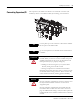
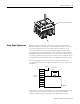
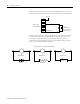
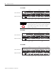
The controller terminal block layouts are shown below. The shading on the
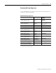
labels indicates how the terminals are grouped. A detail of the groupings is
shown in the table following the terminal block layouts.
Terminal Block Layouts
1763-L16AWA
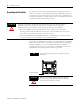
TIP
This symbol denotes a protective earth ground
terminal which provides a low impedance path
between electrical circuits and earth for safety
purposes and provides noise immunity
improvement. This connection must be made for
safety purposes on AC-powered controllers.
This symbol denotes a functional earth ground
terminal which provides a low impedance path
between electrical circuits and earth for non-safety
purposes, such as noise immunity improvement.
AC
COM
NOT
USED
VAC O/0
VDC
VAC O/1
VDC
VAC O/2
VDC
VAC O/3
VDC
VAC O/4
VDC
VAC O/5
VDC
NOT
USED
NOT
USED
L1 L2/N
100-240 VAC
NOT
USED
I/1I/0 I/2 I/3
AC
COM
I/4 I/5
IA
COM
IV1(+) IV2(+)I/6 I/7 I/8 I/9
Input Terminal Block
Output Terminal Block
Group 1 Group 2
G
r
o
u
p
0
G
r
o
u
p
1
G
r
o
u
p
2
G
r
o
u
p
3
G
r
o
u
p
4
G
r
o
u
p
5
Group 0