
User manual

Publication 1763-UM001E-EN-P - March 2015
Wiring Your Controller 63
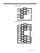
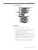
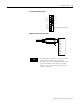
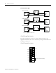
1762-IQ8OW6 Wiring Diagram
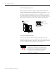
Analog Wiring
Consider the following when wiring your analog modules:
• The analog common (COM) is not connected to earth ground inside the
module. All terminals are electrically isolated from the system.
• Channels are not isolated from each other.
• Use Belden 8761, or equivalent, shielded wire.
• Under normal conditions, the drain wire (shield) should be connected to
the metal mounting panel (earth ground). Keep the shield connection to
earth ground as short as possible.
• To ensure optimum accuracy for voltage type inputs, limit overall cable
impedance by keeping all analog cables as short as possible. Locate the
I/O system as close to your voltage type sensors or actuators as
possible.
• The module does not provide loop power for analog inputs. Use a
power supply that matches the input transmitter specifications.
IN 6
IN 4
IN 3
IN 1
IN 5
IN 2
IN 0
OUT 4
OUT 2
OUT 0
VAC
VDC
VAC
VDC
DC
COM 1
OUT 3
OUT 1
IN 7
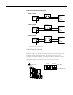
L1 or +DC
L1 or +DC
-DC (Sinking)
+DC (Sourcing)
Connected Internally
+DC (Sinking)
-DC (Sourcing)
L2 or -DC
OUT 5
+DC (Sinking)
-DC (Sourcing)
-DC (Sinking)
+DC (Sourcing)
DC
COM 0
CR
CR
CR
CR