
Specifications


B =
1
:
2è × %
+1
× 4
+
;
:
*V
;
PCB Connections
www.ti.com
In order to obtain the lowest level distortion measurements, it is important to make an oscilloscope chassis
ground connection to the power supply star ground point while NOT using the scope probe ground clip.
Connecting the scope probe ground clip to AGND, while probing the output stage, may significantly
increase distortion.
Due to the physical size limitation of providing large valued reservoir capacitors on the PCB, it is expected
that the user provide a low-inductance connection to either a low impedance power supply or bulk
capacitance.
In order to minimize amplifier distortion in a lab environment, it is recommended to provide high-valued
reservoir capacitors between the lab power supply and the PCB amplifier module. It is also recommended
to keep connections between the reservoir capacitors and the amplifier module as short as possible.
39,000µF of reservoir capacitance per supply rail was used for bench testing to obtain the performance
indicated in this document.
4.5 Mute Function
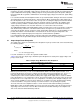
A reference voltage is used for the mute circuit in the EF125WT1 FET amplifier module, as shown in
Figure 5. This reference voltage allows varying power supply voltages to be applied to the LME49830
without continually adjusting the mute resistance. The mute current is set to 160μA using the on-board
(+12V) mute voltage. J
11
and J
12
allow for an external mute voltage of 2.6V to 5V to be used or the user
can adjust the value of the R
M2
mute resistor for any desired voltage.
Figure 5. Mute Circuit Reference Voltage
Detailed design information for proper mute circuit operation and reference voltage set up can be found in
the LME49830 datasheet. Also shown in the datasheet is the excellent level of mute attenuation of -120dB
for audio signals. The LME49830 mute function has a smooth turn-on/off transition so that clicks and pops
are minimized. Adding a capacitor to the MUTE pin can totally eliminate any clicks and pops that may
occur with the trade-off being a delay when changing modes. A 47μF Mute capacitor is supplied on the
EF125WT1 FET PCB for a virtually silent mode change with minimal delay.
4.6 Gain and Frequency Response
The amplifier module is configured as non-inverting mode. The gain is set by:
A
V
= 1 + R
F1
/ R
I
(V/V) (11)
The gain is set to 28.3V/V (29dB) with R
F1
set to 6.8kΩ and R
I
set to 249Ω. The low frequency response is
set by the combination of C
I1
and R
I
by the equation:
(12)
10
AN-1850 LME49830TB Ultra-High Fidelity High-Power Amplifier Reference SNAA058B–July 2008–Revised May 2013
Design
Submit Documentation Feedback
Copyright © 2008–2013, Texas Instruments Incorporated