
Installation Instructions


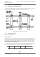


Table Of Contents
- Installation & Commissioning Handbook Vol. 1
- RECORD OF CHANGES
- TABLE OF CONTENTS
- SECTION 1 ANTENNA INSTALLATION PROCEDURE
- 1 Civil Work Checks
- 2 Localizer Antenna System Assembly
- 3 Glidepath antenna system assembly/towers 10m and 15m
- 4 Near field monitor
- 5 Marker beacon installation antenna assembly
- SECTION 2 SHELTER INSTALLATION
- 1 General
- 2 Mechanical installation LLZ/GP
- 3 Electrical Installation LLZ/GP
- 4 Mechanical Installation Marker Beacon
- 5 Electrical installation marker beacon
- 6 Remote Control Connections (TWR)
- SECTION 3 ANTENNA SYSTEMS ADJUSTMENTS PROCEDURE
- 1 NM 3522 6 elements antenna system adjustments - LLZ
- 1.1 Mechanical alignment of antenna array
- 1.2 Electrical measurements
- 1.3 Course sector width adjustment
- 1.4 Monitor combining unit (MCU) adjustments
- 1.5 Near field monitor adjustments
- 1.6 DC-Loop adjustment and testing
- 2 NM 3523B 12 Elements antenna system adjustments - LLZ (Single frequency)
- 3 NM 3524 12 Elements antenna system adjustments - LLZ (Dual frequency)
- 3.1 Mechanical alignment of antenna array
- 3.2 Electrical measurements
- 3.2.1 CSB and SBO cables
- 3.2.2 CSB/SBO phasing
- 3.2.3 Antenna cable lengths (Electrical phase equality)
- 3.2.4 Antenna pair phasing
- 3.2.5 Phase and amplitude transfer measurement
- 3.2.6 Antenna return loss
- 3.3 Course sector width adjustment
- 3.4 Monitor combining unit (MCU) adjustments
- 3.5 Near field monitor adjustments
- 3.6 DC-Loop adjustment and testing
- 4 NM 3525 24 Elements antenna system adjustments - LLZ
- 4.1 Mechanical alignments of antenna array
- 4.2 Electrical measurements
- 4.3 Course sector width adjustments
- 4.4 Monitor combining unit (MCU) adjustments
- 4.5 Near field monitor adjustments
- 4.6 DC-Loop adjustment and testing
- 5 NM 3526 16 Elements antenna system adjustments - LLZ
- 5.1 Mechanical alignments of antenna array
- 5.2 Electrical measurements
- 5.3 Course sector width adjustment
- 5.4 Monitor combining unit (MCU) adjustments
- 5.5 Near field monitor adjustments
- 5.6 DC-Loop adjustment and testing
- 6 NM 3543 Null reference antenna system adjustments - Glide path
- 6.1 Mechanical alignment of mast and antennas
- 6.2 Electrical measurements
- 6.3 CSB/SBO Phasing and sector width adjustment
- 6.4 Monitoring combining unit (MCU) adjustments
- 6.5 Location of near field antenna position
- 7 NM 3544 Sideband reference antenna system adjustment - Glide path
- 7.1 Mechanical alignment of mast and antennas
- 7.2 Initial electrical measurements
- 7.3 CSB/SBO Phasing
- 7.4 Sector width adjustment
- 7.5 Monitor combining unit (MCU) adjustments
- 7.6 Location of near field antenna position
- 7.7 Antenna distribution unit (ADU) phase and amplitude check
- 8 NM 3545 M-Array antenna system adjustments - Glide path
- 8.1 Mechanical alignment of mast and antennas
- 8.2 Initial electrical measurements
- 8.3 CSB/SBO Phasing
- 8.4 Sector width adjustment
- 8.5 Monitor combining unit (MCU) MOA 338D adjustments
- 8.6 Location of near field antenna position
- 8.7 Antenna distribution unit (ADU) DIA 346A phase and amplitude check
- 9 NM 3561 Single antenna system adjustments - MKR
- 10 NM 3562 Dual antenna system adjustments - MKR
- 1 NM 3522 6 elements antenna system adjustments - LLZ
- SECTION 4 TEST AND ADJUSTEMENTS
- 1 Tests and adjustments LLZ/GP
- 1.1 Configuration Settings
- 1.2 Transmitter Alignments and Calibration
- 1.3 Antenna System Adjustments
- 1.4 Monitor Alignment and Calibration.
- 1.5 Monitor Alarm Setting Procedure
- 1.6 Maintenance Limit Adjustments
- 1.7 Adjustment points
- 2 Tests and adjustments marker beacon
- 1 Tests and adjustments LLZ/GP
- SECTION 5 GROUND COMMISIONING REFERANCE DOCUMENTS
- SECTION 6 APPENDIX
- Diagram 1 Relative SBO vs CS Width, NM3522.
- Diagram 2 Relative SBO vs CS Width, NM3523B.
- Diagram 3 Relative SBO vs CS Width, NM3524.
- Diagram 4 Relative SBO vs CS Width, NM3525.
- Diagram 5 Relative SBO vs CS Width, GP antenna systems.
- Diagram 6 GP angle vs relative antenna height, NM3545.
- Diagram 7 GP angle vs relative antenna height, NM3544.
- Diagram 8 GP angle vs relative antenna height, NM3543.
- SECTION 1 ANTENNA INSTALLATION PROCEDURE

1250$5&
1DYLD$YLDWLRQ$6
,167580(17/$1',1*6<67(0
,167$//$7,21&200,66,21,1*+$1'%22.
2 Localizer Antenna System Assembly
2.1 Positioning of antenna frame work
By means of a theodolite determine the exact position of the extended runway centre line and
mark the 90 degrees angle points on each concrete slab. See Figure 2-1.
Figure 2-1 Alignment of antenna frame work.
2.2 Framework assembly
See Vol. 2 Section 2 Chapter 6.
See also Figure 2-1
On middle aluminium bar mark exact centre. Position the bar accurately so the marks line up
with the extended centre line. Affix the two clamping angles.The remaining aluminium bars of
the front part can now be assembled across the concrete fundaments. Use junction plates
between each bar. On each fundament (left and right) adjust to the same distance between
the theodolite mark and the aluminium bar.
The al. Bars are numbered at each end on top side. The center bar is marked 1-1 and the next
bar on each side is marked 1-2. The third bar on each side is marked 2-3 and so on.
Figure 2-2
22 11 11 22 3