
Cut Sheet


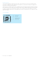

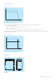
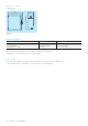
Table Of Contents

2 - Power supply CP-E 24/5.0 | Data sheet
Functions
XXXXXXXXXXXXXXX
1
OUTPUT L+, L+, L-, L-:
terminals – output
2
INPUT L, N, PE:
terminals – input
3
13-14:
terminals – signalling contact
4
OUTPUT LOW:
red LED – output voltage too low
5
OUTPUT OK:
green LED – output voltage OK
6
OUTPUT Adjust:
potentiometer – adjustment of the output voltage
7
single/parallel:
sliding switch – adjustment of single or parallel operation
8
Circuit diagram
Application
The primary switch mode power supply offers two voltage input ranges. This enables the supply with AC or DC.
Furthermore it is equipped with two generous capacitors, which ensure mains buffering of at least 30 ms (at 230 V AC).
That is why the devices can be used worldwide also in high fluctuating networks and battery-powered plants.
Operating mode
By means of the potentiometer “OUTPUT Adjust” the output voltage can be adjusted within a range of 22.5 to 28.5 V DC.
Thus, the power supply can be optimally adapted to the application, e.g. compensating the voltage drop caused by a long
line length.
The green LED “OUTPUT OK” is lightening during proper operation.
The red LED “OUTPUT LOW” is lightening when the output voltage is too low.
Switch “single/parallel” for selection of single or parallel operation.
Signalling contact 13-14 (max. 60 V DC / 0.3 A) is ON when the output voltage is more than 75 %.
3
1
2
4
5
8
7
6