
Cut Sheet


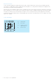

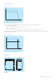
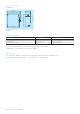
Table Of Contents

Data sheet | Power supply CP-E 24/5.0 - 3
Installation
Mounting
The switch mode power supply can be snapped on a DIN rail according to IEC/EN 60715 as shown in the accompanying
picture. For that the device is set with its mounting rail slide on the upper edge of the mounting rail and locked by lifting it
downwards.
2CDC272017F0b08
2CDC 272 017 F0b08
Demounting
Remove the switch mode power supply as shown in the accompanying picture. For that the latching lever is pulled
downwards by means of the screwdriver. Alternatively you can press the unlock button to release the device. Then in both
cases the device can be unhinged from the mounting rail edge and removed.
2CDC272018F0b08
2CDC 272 018 F0b08
Mounting position
The devices have to be mounted horizontally with the input terminals on the bottom. In order to ensure a sufficient
convection, the minimum distance to other modules should not be less than 25 mm in vertical and horizontal direction.
2CDC272019F0b08
2CDC 272 019 F0b08