
Cut Sheet


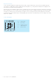

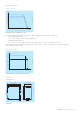
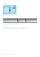
Table Of Contents

4 - Power supply CP-E 24/5.0 | Data sheet
Electrical connection
Connect the input terminals L and N. The protective earth conductor PE must be connected. The installation must be
executed acc. to EN 60950, provide a suitable disconnecting device (e. g. line protection switch) in the supply line. The
input side is protected by an internal input fuse.
Rate the lines for the maximum output current (considering the short-circuit current) or provide a separate fuse protection.
We recommend to choose the cable section as large as possible in order to minimize voltage drops. Observe the polarity.
The device is overload, short-circuit and open-circuit proof. The secondary side of the power supply unit is electrically
isolated from the input and internally not earthed (SELV) and can therefore be earthed by the user according to the needs
with L+ or L- (PELV).
Connection diagram
L- L- L+ 13 14
PE
NL
L+
L-
L+
L
N
PE
PWM
2CDC 272 023 F0b08
2CDC272023F0b08
L+, L- Output voltage
L, N Input voltage
13-14 Signalling contact for
output voltage OK
PE Protective earth