Installation manual Terra AC(UL 80A) © Copyright ABB.
Copyright All rights to copyrights, registered trademarks, and trademarks reside with their respective owners. Copyright ® ABB EV Infrastructure. All rights reserved.
About this document Contents 1 2 About thisdocument ......................................................... 6 1.1 Function of this document .............................................................................. 6 1.2 Target group ................................................................................................ 6 1.3 Revision history ............................................................................................. 6 1.4 Language ................................
About this document 3 Safety ............................................................................ 22 3.1 Liability ..................................................................................................... 22 3.2 Required qualifications for the installation engineer ............................................... 22 3.3 Personal protective equipment ........................................................................... 22 3.4 FCC compliancestatement .........................
9 10 8.1 About this document General commissioning procedure ................................................................... 37 8.2 Energize the EVSE ........................................................................................ 38 8.3 Set up the EVSE ........................................................................................... 38 Troubleshooting ............................................................. 39 9.1 Troubleshooting procedure ...............................
About this document 1 About this document 1.1 Function of this document The document is only applicable for this EVSE (Terra AC), including the variants and options listed in section 11.1. The EVSE from here on in the document is referred to as the EVSE. The document gives the information that is necessary to do these tasks: 1 Installation 2 Commissioning 1.2 Target group The document is intended for qualified installation engineers.
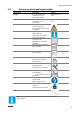
About this document 1.9 General symbols and signal words Signal word Danger Warning Caution Note - - Description If you do not obey the instruction, this can cause injury or death If you do not obey the instruction, this can cause injury. If you do not obey the instruction, this can cause damage to the EVSE or to property A note gives more data, to make it easier to do the steps, for example. Refer to section 1.10.
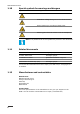
About this document 1.10 Special symbols for warnings and dangers Symbol Risk type General risk Hazardous voltage that gives risk of electrocution Risk of pinching or crushing of body parts Rotating parts that can cause a risk of entrapment Note: It is possible that not all symbols are present in this document. 1.
About this document 1.
About this document Term Definition Contractor Third party that the owner or site operator hires to do engineering, civil and electrical installation work Grid provider Company that is responsible for the transport and distribution of electricity Local rules All rules that apply to the EVSE during the entire lifecy- cle of the EVSE. The local rules also include the national laws and regulations.
Description 2 Description 2.1 Short description The EVSE (Terra AC) is an AC charging station that you can use to supply electricity to an EV. The Terra AC offers tailor-made, intelligent and network charging solutions for your company or home. The EVSE can connect to the internet via GSM, WiFi or LAN. 2.2 Intended use The EVSE is intended for the AC charging of EVs. The EVSE is intended for indoor or outdoor use.
Description A Serial number E B C D Part number of the EVSE Product model number Barcode with the serial number of the EVSE F G H Barcode with the part number of the EVSE Power rating of the EVSE Ambient temperature Mass of the EVSE Note: The data in the illustration is only an example. Find the type plate on your EVSE to see the applicable data. Refer to section 2.6.2. 2.
Description 2.5 Overview 2.5.1 Overview of the system A B E F G D A B C D 2.5.2 C EVSE AC grid input EV Parking space E F on G RFID card or smartphone Structure to install the EVSE EV charge cable Part Function EVSE Refer to section 2.2. Structure To install the EVSE on and to keep the EVSE in position.
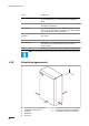
Description G F H I E A B A B C D E 14 Socket for the EV charge cable Openings for the smart meter connections Openings for the Ethernet cable Opening for the AC input cable LED indicators F G H I C D Cabinet cover Enclosure RFID reader Type plate Part Function Socket for the EV charge cable To hang the EV charge cable Openings LED indicators Openings for the cables that go into the EVSE To show the status of the EVSE and the charge session. Refer to section 2.8.1.
Description 2.6 Options 2.6.1 Display A A Display For more data about the display, refer to section 2.10. 2.6.2 EV charge cable, Type 1 (North America, Terra AC Wx-Px-xxxxx) 2.6.3 3G/4G Communication You can connect to a 3G/4G network. 2.6.4 Load management Load management makes sure that the available capacity of the building or home is not exceeded. A number of devices share a grid connection, that has a maximum capacity.
Description 2.
Description Table 3: Cable and car detection, and car authorization LED Status of the LED Status of the EVSE On A car is connected. The connection is authorized. Off No car connected. Flashing A car is connected, waiting for authorization. Table 4: Internet connection LED Status of the LED Status of the EVSE On Connected to the internet Off Not connected to the internet Flashing The internet connection is set up. Table 5: EVSE on/off LED 2.
Description 2.9.2 Standby/Idle screen A B Total : 325.634,622 KWh 30.07.2020 10:30 SN : TACW2240120G4567 C v 00.55.19 D E D Serial number A Total delivered energy E Firmware version (MID certified) B Date C Guide The display shows the Standby/Idle screen when the EVSE is in idle status. Then, the EVSE is available for a charge session. 2.9.3 Authorization screen The display shows different Authorization screens, dependent on the situation.
Description 2.9.4 Preparing to charge screen Total : 325.637,622 kWh 30.07.2020 10:30 SN : TACW2240120G4567 2.9.5 v 00.55.19 Charging screen The display shows the Charging screen during the charge session.
Description 2.9.6 Charging completed screen A Total : B 30.07.2020 09:35 325.637,622 kWh 30.07.2020 07:30 - 30.07.2020 09:29 23,122kWh 02:59 SN : TACW2240120G4567 A 2.9.7 v 00.55.19 Start and end time B Energy delivered and duration of the charge session Fault detected screen The display shows different Fault detected screens, dependent on the type of fault. Disconnect the charge cable and connect it again: Total : 325.637,622 kWh 30.07.2020 09:35 0x0010 SN : TACW2240120G4567 v 00.55.
Description Total : 325.637,622 kWh SN : TACW2240120G4567 30.07.2020 10:30 v 00.55.
Safety 3 Safety 3.1 Liability The manufacturer is not liable to the purchaser of the EVSE or to third parties for damages, losses, costs or expenses incurred by the purchaser or third parties if any target group mentioned in the related documents does not obey the rules below: 1 Obey the instructions in the related documents. Refer to section 1.11. 2 Do not misuse or abuse the EVSE. 3 Only make changes to the EVSE, if the manufacturer approves in writing of the changes.
Safety Symbol Description Safety shoes Safety glasses 3.4 FCC compliance statement Caution: Changes or modifications not expressly approved by the party responsible for compliance could void the user's authority to operate the equipment. This device complies with Part 15 of the FCC Rules.
Safety 3 3.7 you are qualified for. Obey the local rules and the instructions in this manual. If the local rules contradict the instructions in this manual, the local rules will apply. If and to the extent permitted by law, in case of inconsistency or contradiction, between any requirements or procedure contained in this document and any such local rules, obey the stricter between the requirements and procedures specified in this document and the local rules.
Safety 3.8 Discard the EVSE or parts of the EVSE Incorrect waste handling can have a negative effect on the environment and human health due to potential hazardous substances. With the correct disposal of this product, you contribute to reuse and recycling of materials and protection of the environment. 1 Obey the local rules to discard parts, packaging material or the EVSE. 2 Discard electrical and electronic equipment separately in compliance 3 4 3.
Safety • • • • • • • • Make sure that adults supervise this EVSE is when it is used around children. Do not put fingers into the EV connector. Do not use this product if the flexible power cord or EV charge cable is frayed, has broken insulation, or any other signs of damage. Do not use this EVSE if the enclosure or the EV connector is broken, cracked, open, or shows any other indication of damage.
Installation 4 Installation 4.1 General installation procedure Preliminary requirements 1. 2. • All required permits to agree with the local rules are granted. The AC input cable is available. • There is no voltage on the AC input cable during the complete installation procedure. Tools for installation. Refer to section 11.7. Procedure 1. Unpack the EVSE. Refer to section 4.2. 2. Prepare the site. Refer to chapter 5. 3. Do the mechanical installation. Refer to section 6.1. 4.
Site preparation 5 Site preparation 5.1 Select the site 1. 2. 3. 5.2 Find a suitable site on a wall. For the specifications of the wall, refer to section 10.7. Make sure that the correct power supply is available. For the power supply specifications, refer to section 10.10. Obey the space requirements. Refer to section 10.9.2. Prepare the site (North America, Terra AC Wx-Px-xxxxx) Preliminary requirements 1. The site must be suitable to install the EVSE. Refer to section 5.2. Procedure 1.
Mechanical installation 6 Mechanical installation 6.1 General mechanical installation procedure Note: The mounting screws and plugs that are included in the delivery are serviceable for a brick wall. If you want to mount the EVSE on a different type of wall, contact your local representative of the manufacturer (ABB EV Infrastructure). 1. Prepare the holes for the mounting screws. Refer to section 6.2. 2. Move the socket. Refer to section 6.3. 3. Install the EVSE on the site. Refer to section 6.4. 6.
Mechanical installation 6.3 Move the socket Preliminary requirements 1. The plugs for the mounting screws are installed. • Screwdriver Procedure 1. Remove 2 screws and remove the front cover. 2. Remove 11 screws and remove the maintenance door. 3. Remove the screw(A) on the left side of socket. 4. Move the socket away. 6.4 Install the upper mounting screws Preliminary requirements 1. The plugs for the upper and lower mounting screws are installed. Procedure 1. 2.
Electrical installation 7 Electrical installation 7.1 General electrical installation procedure Preliminary requirements • Procedure 1. Install the AC input cable. • • 2. Install the Ethernet cable. • • 3. 5. 7.2 7.2.1 Insert the Ethernet cable. Refer to section 7.4.1. Connect the Ethernet cable. Refer to section 7.4.2. If necessary, install the cables for smart meter communication. • • 4. Insert the AC input cable. Refer to section 7.2. Connect the AC input cable. Refer to section 7.3.
Electrical installation 7.2.2 Install the lugs or cold-pressed terminal for L1,L2 (1) Lugs Preliminary requirements • Torque Screwdriver • • Lugs. Refer to section 10.6. • AC input cable (1 phase) Procedure 1. 2. 3. 4. Loosen the screws(A) Strip the wires. For the specification, refer to section 10.12.1.. Insert the wire in the side 1 of lugs. Tighten the screws(A) to the correct torque. For the specification, refer to section 10.
7.2.3 Electrical installation Insert the AC input cable Preliminary requirements • Screwdriver • AC input cable Procedure 1. Remove the grommet (A) from the EVSE. 2. 3. Install the conduit. Strip the wires. For the specification, refer to section 10.13. Put the AC input cable (B) through the inlet hole. 4. Max.
Electrical installation 7.3 Connect the AC input cable Preliminary requirements • Torque screwdriver Procedure 4. Connect the below wires: 1. 2. 3. 5. 6. Earthing (grounding) wire (A) L2 AC input wire (B) L1 AC input wire (C) Tighten the screws(D) to the correct torque. For the specification, refer to section 10.14. Install the protect cover(F). 7.4 Communication connections 7.4.1 Insert the Ethernet cable Preliminary requirements 1. 2. The cabinet cover is removed.
Electrical installation 7.4.2 Connect the Ethernet cable Preliminary requirements 1. The Ethernet cable is inserted. Refer to section 7.4.1. If your EVSE has two Ethernet connections, it is possible to connect multiple EVSEs in a chain. Only the first EVSE is connected to the PC, router or gateway. Only the Ethernet connection is shared, there is no communication between the EVSEs. Procedure 1. 2. 3. Put the RJ45 plug (A) of the Ethernet cable in the primary Ethernet RJ45 socket (B).
Electrical installation 7.4.4 Connect the wires for the smart meter communication Connect the smart meter with ModBus RTU (RS485) to the EVSE. Preliminary requirements • Slotted screwdriver • • Smart meter with ModBus RTU interface Wire for RS485. Refer to section 10.12.3. Obey the local rules for the correct wire insulation rating. Procedure 1. 2. 3. 4. Remove the plug (A) of the terminal block (B) from the terminal block (B) of the smart meter connection. Connect the wires: a.
Commissioning 8 Commissioning 8.1 General commissioning procedure Preliminary requirements • Mobile device Warning: Only use this commissioning procedure for domestic use of the EVSE and commissioning with the TerraConfig app. For all other methods of commissioning, do not do the commissioning. Contact your local representative of the manufacturer. Refer to section 1.12.
Commissioning 1. Download the TerraConfig app. • • 2. 3. 8.2 For an Android OS mobile device, go to Google Play Store. For an iOS mobile device, go to Apple Store. Energize the EVSE. Refer to section 8.2. Set up the EVSE. Refer to section 8.3. Energize the EVSE 1. Close the breaker that supplies the power to the EVSE. Warning: • • • • 8.3 Hazardous voltage Be careful when you work with electricity. The power supply comes on.
Troubleshooting 9 Troubleshooting 9.1 Troubleshooting procedure 1. 2. 9.2 Try to find a solution for the problem with the aid of the information in this document. If you cannot find a solution for the problem, contact your local representative of the manufacturer. Refer to section 1.12. Troubleshooting table Problem Possible cause Possible solution The current is too high There is an overload on the 1. EV side 2.
Troubleshooting Problem Possible cause Possible solution There seems to be There is residual current in 1. residual current in the charging circuit. the charging circuit 2. De-energize the EVSE. Refer to section 10.3. Contact your local representative of the manufacturer or a qualified electrical contractor. Refer to section 1.9. The monitoring sensor for Replace the monitoring sensor residual current has a fail- for residual current. ure.
Troubleshooting Problem The EV connection or authorization process fails Possible cause Possible solution The EV charge cable is defective. 1. 2. Examine the EV charge cable. If the standard supplied EV charge cable is defective, replace the EV charge cable. Refer to section 7.5.2. The EV charge cable is defective. 1. 2. Examine the EV charge cable. If the standard supplied EV charge cable is defective, replace the EV charge cable. Refer to section 7.5.2. The EV charge cable is not 1.
Technical data 10 Technical data 10.1 EVSE Type The EVSE type is a code. The code has 10 parts: A1 - A10. Code part Description Value Meaning of the value A1 Brand name Terra AC - A2 Type W Wallbox C Column 4 3.7 kW 7 7.
Technical data • • • • • • • • 10.2 A4 = Cable type, cable = Type 1 A5 = 8 m A6 = authorization = RFID enabled A7 = Ethernet = double A8 = metering = Certified for MID A9 = SIM slot = applicable A10 = display = yes The '0' is an empty field. General specifications Parameter Specification Safety standards • • • Certification UL 2594, UL 2231-1, UL 2231-2, UL 1998 NMX-J-667-ANCE CSA C22.2. NO.
Technical data 10.3 10.4 10.5 Ambient conditions Parameter Value Operation temperature -30°C4 to +55°C Storage temperature -40°C to +85°C Storage conditions Indoor, dry Relative humidity <95%, non-condensing Mass EVSE type Weight [kg] Terra AC wallbox, Type 1 (North America, Terra AC Wx-Px-xxxxx) 12.7(80A) Protective device compliance 10.5.
Technical data 10.6 10.7 Parts included in the delivery Parameter Specification EVSE Refer to the type plate. Refer to section 2.3. Mounting screws M6 x 80 Plugs for mounting screws (servicable for a brick wall) 10x 100 mm Installation template - Size for conduit RFID card 1’’ for AC input 3/4’’ for Smart Meter or Ethernet MIFARE Label with PIN To log in to the TerraConfig app.
Technical data 10.9 Dimensions 10.9.
Technical data 10.9.2 Space requirements for installation Z1 A Z2 A EVSE Parameter Specification [mm] Specification [inches] Z1 > 200 >8 Z2 (indoor use) 450 to 1200 18 to 48 Z2 (outdoor use) 600 to 1200 24 to 48 10.10 AC input specifications 10.10.1 General specifications Parameter Specification Frequency 50 Hz or 60 Hz Overvoltage category Category III Protection Overcurrent Overvoltage Undervoltage Earth fault, including DC leakage protection5 Integrated surge protection 10.
Technical data 10.11 General logic interface specifications Parameter Specification Connectivity Mobile communication with Nano-SIM socket type M2M (Machine To Machine) • • • Smart meter communication Modbus RTU (RS485) Modus TCP/IP Ethernet 1x 10/100 BaseT, RJ45 Socket Extra ethernet (daisy chain) 1x 10/100 BaseT, RJ45 Socket WiFi (WAN) IEEE 802.11 b/g/n, 2.4 GHz Bluetooth BLE 5.0 RFID MIFARE ISO/IEC 14443A RFID cards Compatible mobile device operating sys- • tems • 10.
Technical data 10.12.2 10.12.3 Ethernet cable specifications Parameter Specification EVSE connector type RJ45 Modular jack Cable type Category 5 (Cat 5) RS485 cable specifications The RS485 cable specifications apply to smart meter ModBus RTU communication.
Technical data Required torque 0.5 Nm Parameter Specifications Strip length 5 mm Terminal connections • • PE/Shield: Contact input terminal 1 or 2 Configuration input: Contact input terminal 2 or 1 Wire AWG and cross section: based on a copper wire type 10.12.5 Dry contacts output The dry contacts input is the single contact in the EVSE.
10.14 Technical data Torque specifications Parameter Specification [Nm] Terminal block for the AC input 2.5 Terminal block for the communication wires and the smart meter connections 0.5 Terminal block for the EV charge cable 2.5 Mounting screws 4.