
User`s manual

44 Installing the drive
ACH550-01 User's Manual
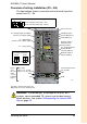
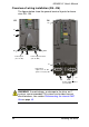
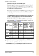
Overview of wiring installation (R5…R6)
The figures below show the general terminal layouts for frame
sizes R5…R6.
WARNING! To avoid danger, or damage to the drive, on IT
systems, corner-grounded TN systems and residual current
circuit breakers, see section Disconnecting the internal EMC
filter on page 45.
R5
X0013
Power output to motor
(U2, V2, W2)
Power input
(U1, V1, W1)
GND
F2
F1
F1
PE
GND
PE
Power output to motor
(U2, V2, W2)
F2
R6
GND
Power input
3-phase: U1, V1, W1
1-phase: U1 (live), W1