User’s Manual ACS550-PD Stock 3R Irrigation Packaged Drive Supplement to ACS550-U1 User’s Manual
ACS550 Drive Manuals GENERAL MANUALS ACS550-U1 User’s Manual (1…200 HP) • Safety • Installation • Start-Up • Embedded Fieldbus • Fieldbus Adapter • Diagnostics • Maintenance • Technical Data ACS550 Technical Reference Manual (available in electronic format only) • Detailed Product Description • Practical Engineering Guides © 2014 ABB Inc. All Rights Reserved.
ACS550-PD 3R Irrigation Packaged Drive Table of Contents Table of Contents Safety Use of Warnings and Notes...............................................4 Installation Application........................................................................5 Input Disconnect Features and Functions.........................6 Installation Flow Chart.......................................................7 Lifting................................................................................
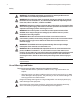
ACS550-PD 3R Irrigation Packaged Drive Safety WARNING! The ACS550 adjustable speed AC drive with Input Disconnect should ONLY be installed by a qualified electrician. WARNING! Even when the motor is stopped, dangerous voltage is present at the Power Circuit terminals U1, V1, W1 and U2, V2, W2 and, depending on the frame size, UDC+ and UDC-, or BRK+ and BRK-. WARNING! Dangerous voltage is present when input power is connected.
ACS550-PD 3R Irrigation Packaged Drive 5 Installation Study these installation instructions carefully before proceeding. Failure to observe the warnings and instructions may cause a malfunction or personal hazard. WARNING! Before you begin read “Safety” on page 1. WARNING! When the ACS550 with Input Disconnect is connected to the line power, the Motor Terminals T1, T2, and T3 are live even if the motor is not running.
ACS550-PD 3R Irrigation Packaged Drive The following figures show the front view of the ACS550 Drive with Input Disconnect standard configurations, and identify the major components. UL Type / NEMA 3R Enclosures Operating Handle for Disconnect Switch Note! UL Type 3R enclosures are designed to be mounted on a wall. See section “Prepare the UL Type 3R ACS550 for UNISTRUT® mounting” for more details.
ACS550-PD 3R Irrigation Packaged Drive 7 Installation Flow Chart The installation of Input Disconnect configurations for ACS550 drives follows the outline below. The steps must be carried out in the order shown. At the right of each step are references to the detailed information needed for the correct installation of the unit. Note! References in the middle column below are to the ACS550-U1 User’s Manual. References in the third column below are to this manual.
ACS550-PD 3R Irrigation Packaged Drive Preparing for Installation (Supplement to ACS550-U1 User’s Manual) Lifting the Drive
ACS550-PD 3R Irrigation Packaged Drive 9 Preparing for Installation (Supplement to ACS550-U1 User’s Manual) Drive Identification To identify the type of device you are installing, refer to the type code number on the device identification label. • Wall mounting base drives – label attached on the side surface of the heat sink. • Packaged drive – label attached to outside surface on the left ide of the enclosure. • Enclosure with hinged cover/door – label on inside surface of the cover/door.
ACS550-PD 3R Irrigation Packaged Drive Suitable Mounting Location For selecting a suitable mounting location for configurations, refer to: • Preparing for installation in the ACS550-U1 User’s Manual, and • The Technical Data section of this manual for information on dimensions and weights. Installing the Drive (Supplement to ACS550-U1 User’s Manual) WARNING! Metal shavings or debris in the enclosure can damage electrical equipment and create a hazardous condition.
ACS550-PD 3R Irrigation Packaged Drive Prepare the UL Type 3R ACS550 for UNISTRUT® mounting The ACS550 UL Type 3R cabinet frame sizes are designed to be mounted on a solid vertical surface or using UNISTRUT.
ACS550-PD 3R Irrigation Packaged Drive Installing the Wiring (Supplement to ACS550-U1 User’s Manual) Wiring Requirements Refer to the “Wiring Requirements” Section in the ACS550-U1 User’s Manual. The requirements apply to all ACS550 drives. In particular: • Use separate, metal conduit runs for the following different classes of wiring: – Input power wiring. – Motor wiring. – Control/communications wiring. • Properly and individually ground the drive, the motor and cable shields.
ACS550-PD 3R Irrigation Packaged Drive Typical Power Connections for Single and Three Phase 13
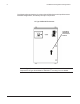
ACS550-PD 3R Irrigation Packaged Drive ACS550-PD 15-200 hp *Typical ACS550 3R irrigation panel layout
ACS550-PD 3R Irrigation Packaged Drive 15 Maintenance Maintenance Intervals If installed in an appropriate environment, the drive requires very little maintenance. This table lists the routine maintenance intervals recommended by ABB. Maintenance Configuration Interval Check/replace UL Type 3R/NEMA 3R enclosure air filters UL Type / NEMA 3R enclosures Check every 3 months. Replace as needed. Instruction Check and clean heatsink.
ACS550-PD Packaged Drive with Disconnect Typical Control Schematic
ACS550-PD Packaged Drive with Disconnect 17 Technical Data Ratings (Supplement to ACS550-U1 User’s Manual) Note! The ratings listed below are exceptions to the ratings listed in the ACS550-U1 User’s Manual.
ACS550-PD Packaged Drive with Disconnect Input Power Connections and Power Connection Terminals (Supplement to ACS550-U1 User’s Manual) 1-Phase 240V Drive Input Fuse Rating HP ABB Product Code Incoming Power Connections Ground Output Connections to Motor Lugs Tightening Amps Bussman Minimum Maximum Torque (600V) Type Wire Size Wire Size (lb/ft) 15 ACS550-PD-088A-2+C192 100 JJS-110 #8 1/0 55 20 ACS550-PD-114A-2+C192 150 JJS-150 #4 300MCM 200 25 ACS550-PD-143A-2+C192 200 JJS-200
ACS550-PD Packaged Drive with Disconnect 19 Input Power Connections and Power Connection Terminals (Supplement to ACS550-U1 User’s Manual) 3-Phase 240V Drive Input Fuse Rating Incoming Power Connections HP ABB Product Code 25 ACS550-PD-075A-2+C192 100 JJS-100 #8 1/0 55 30 ACS550-PD-088A-2+C192 110 JJS-110 #8 1/0 55 40 ACS550-PD-114A-2+C192 150 JJS-150 #4 300MCM 200 50 ACS550-PD-143A-2+C192 200 JJS-200 #4 300MCM 200 60 ACS550-PD-178A-2+C192 250 JJS-250 #4 300MCM 200
ACS550-PD Packaged Drive with Disconnect Input Power Connections and Power Connection Terminals (Supplement to ACS550-U1 User’s Manual) 3-Phase 480V Drive Input Fuse Rating Incoming Power Connections Ground Lugs Output Connections to Motor HP ABB Product Code 40 ACS550-PD-059A-4+C192 80 JJS-80 #8 1/0 55 10 1/0 4 50 ACS550-PD-072A-4+C192 90 JJS-90 #8 1/0 55 10 1/0 4 60 ACS550-PD-078A-4+C192 100 JJS-100 #8 1/0 55 10 1/0 4 75 ACS550-PD-097A-4+C192 125 JJS-125 #4
ACS550-PD Packaged Drive with Disconnect 21 Dimensions and Weights (Supplement to ACS550-U1 User’s Manual) Dimensions: ACS550-PD UL Type / NEMA 3R 1-Phase 240V HP Weight* (lbs) 15 310 20 320 25 330 30 340 40 345 50 350 Height (in) Width (in) Depth (in) 49.00 32.36 22.
ACS550-PD Packaged Drive with Disconnect Applicable Standards Drive compliance with the following standards is identified by the standards “marks” on the type code label. Mark Applicable Standards UL 508C and C22.2 No. 14 UL Standard for Safety, Power Conversion Equipment, second edition and CSA Standard for Industrial Control Equipment UL 508A UL Standard for Safety, Industrial Control Panels C22.2 No.
ACS550-PD 3R Irrigation Packaged Drive 23
3AUA0000162200 REV A Effective 04/18/2014 Subject to change without notice. All rights reserved. ABB Inc. Low Voltage Drives 16250 West Glendale Drive New Berlin, WI 53151 USA Telephone +1 262 785-3200 +1 800 HELP-365 Telefax +1 262 780-5135 Internet www.abb.