
Firmware Manual
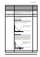
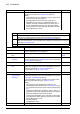


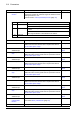
Table Of Contents
- Introduction to the manual
- Using the control panel
- Control locations and operating modes
- Program features
- What this chapter contains
- Drive configuration and programming
- Control interfaces
- Motor control
- Direct torque control (DTC)
- Reference ramping
- Constant speeds/frequencies
- Critical speeds/frequencies
- Speed controller autotune
- Oscillation damping
- Rush control
- Encoder support
- Encoder echo and emulation
- Load and motor feedback
- Position counter
- Encoder error handling
- Reading/writing position counter values through fieldbus
- Configuration of HTL encoder motor feedback
- Example 1: Using the same encoder for both load and motor feedback
- Example 2: Using two encoders
- Example 3: ACS 600 / ACS800 compatibility
- Settings
- Jogging
- Scalar motor control
- Autophasing
- Flux braking
- DC magnetization
- Application control
- DC voltage control
- Safety and protections
- Emergency stop
- Motor thermal protection
- Thermal protection of motor cable
- User load curve
- Other programmable protection functions
- External events (parameters 31.01…31.10)
- Motor phase loss detection (parameter 31.19)
- Earth (Ground) fault detection (parameter 31.20)
- Supply phase loss detection (parameter 31.21)
- Safe torque off detection (parameter 31.22)
- Swapped supply and motor cabling (parameter 31.23)
- Stall protection (parameters 31.24…31.28)
- Overspeed protection (parameter 31.30)
- Ramp stop supervision (parameters 31.32, 31.33, 31.37 and 31.38)
- Custom motor current fault limit (parameter 31.42)
- Local control loss detection (parameter 49.05)
- Automatic fault resets
- Diagnostics
- Miscellaneous
- Application macros
- Parameters
- 01 Actual values
- 03 Input references
- 04 Warnings and faults
- 05 Diagnostics
- 06 Control and status words
- 07 System info
- 10 Standard DI, RO
- 11 Standard DIO, FI, FO
- 12 Standard AI
- 13 Standard AO
- 14 I/O extension module 1
- 15 I/O extension module 2
- 16 I/O extension module 3
- 19 Operation mode
- 20 Start/stop/direction
- 21 Start/stop mode
- 22 Speed reference selection
- 23 Speed reference ramp
- 24 Speed reference conditioning
- 25 Speed control
- 26 Torque reference chain
- 28 Frequency reference chain
- 30 Limits
- 31 Fault functions
- 32 Supervision
- 33 Generic timer & counter
- 35 Motor thermal protection
- 36 Load analyzer
- 37 User load curve
- 40 Process PID set 1
- 41 Process PID set 2
- 43 Brake chopper
- 44 Mechanical brake control
- 45 Energy efficiency
- 46 Monitoring/scaling settings
- 47 Data storage
- 49 Panel port communication
- 50 Fieldbus adapter (FBA)
- 51 FBA A settings
- 52 FBA A data in
- 53 FBA A data out
- 54 FBA B settings
- 55 FBA B data in
- 56 FBA B data out
- 58 Embedded fieldbus
- 60 DDCS communication
- 61 D2D and DDCS transmit data
- 62 D2D and DDCS receive data
- 90 Feedback selection
- 91 Encoder module settings
- 92 Encoder 1 configuration
- 93 Encoder 2 configuration
- 94 LSU control
- 95 HW configuration
- 96 System
- 97 Motor control
- 98 User motor parameters
- 99 Motor data
- 200 Safety
- Additional parameter data
- Fault tracing
- Fieldbus control through the embedded fieldbus interface (EFB)
- What this chapter contains
- System overview
- Connecting the fieldbus to the drive
- Setting up the embedded fieldbus interface
- Setting the drive control parameters
- Basics of the embedded fieldbus interface
- About the control profiles
- The ABB Drives profile
- The Transparent profile
- Modbus function codes
- Exception codes
- Coils (0xxxx reference set)
- Discrete inputs (1xxxx reference set)
- Error code registers (holding registers 400090…400100)
- Fieldbus control through a fieldbus adapter
- What this chapter contains
- System overview
- Basics of the fieldbus control interface
- Setting up the drive for fieldbus control
- Control chain diagrams
- What this chapter contains
- Speed reference source selection I
- Speed reference source selection II
- Speed reference ramping and shaping
- Motor feedback configuration
- Load feedback and position counter configuration
- Speed error calculation
- Speed controller
- Torque reference source selection and modification
- Operating mode selection
- Reference selection for torque controller
- Torque limitation
- Torque controller
- Frequency reference selection
- Frequency reference modification
- Process PID setpoint and feedback source selection
- Process PID controller
- Master/Follower communication I (Master)
- Master/Follower communication II (Follower)
- Further information

Parameters 201
DI6 Digital input DI6 (10.02 DI delayed status, bit 5). 8
DIO1 Digital input/output DIO1 (11.02 DIO delayed status, bit 0). 11
DIO2 Digital input/output DIO2 (11.02 DIO delayed status, bit 1). 12
Other [bit] Source selection (see Terms and abbreviations on page 112 ). -
21.06 Zero speed limit Defines the zero speed limit. The motor is stopped along a
speed ramp (when ramped stop is selected) until the defined
zero speed limit is reached. After the zero speed delay, the
motor coasts to a stop.
30.00 rpm
0.00 … 30000.00
rpm
Zero speed limit. See par.
46.01
21.07 Zero speed delay Defines the delay for the zero speed delay function. The
function is useful in applications where a smooth and quick
restarting is essential. During the delay, the drive knows the
rotor position accurately.
0 ms
Without zero speed delay
:
The drive receives a stop command and decelerates along a
ramp. When actual motor speed falls below the value of
parameter 21.06 Zero speed limit, inverter modulation is
stopped and the motor coasts to a standstill.
With zero speed delay
:
The drive receives a stop command and decelerates along a
ramp. When actual motor speed falls below the value of
parameter 21.06 Zero speed limit, the zero speed delay
function activates. During the delay the function keeps the
speed controller live: the inverter modulates, motor is
magnetized and the drive is ready for a quick restart. Zero
speed delay can be used e.g. with the jogging function.
0 … 30000 ms Zero speed delay. 1 = 1 ms
No. Name/Value Description Def/FbEq16
Speed controller switched off:
Motor coasts to a stop.
21.06 Zero speed limit
Speed
Time
Speed controller remains
active. Motor is decelerated to
true zero speed.
21.06 Zero speed limit
Speed
Time
Delay