
Firmware Manual
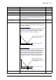
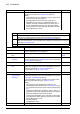
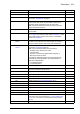
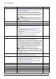


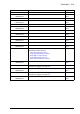
Table Of Contents
- Introduction to the manual
- Using the control panel
- Control locations and operating modes
- Program features
- What this chapter contains
- Drive configuration and programming
- Control interfaces
- Motor control
- Direct torque control (DTC)
- Reference ramping
- Constant speeds/frequencies
- Critical speeds/frequencies
- Speed controller autotune
- Oscillation damping
- Rush control
- Encoder support
- Encoder echo and emulation
- Load and motor feedback
- Position counter
- Encoder error handling
- Reading/writing position counter values through fieldbus
- Configuration of HTL encoder motor feedback
- Example 1: Using the same encoder for both load and motor feedback
- Example 2: Using two encoders
- Example 3: ACS 600 / ACS800 compatibility
- Settings
- Jogging
- Scalar motor control
- Autophasing
- Flux braking
- DC magnetization
- Application control
- DC voltage control
- Safety and protections
- Emergency stop
- Motor thermal protection
- Thermal protection of motor cable
- User load curve
- Other programmable protection functions
- External events (parameters 31.01…31.10)
- Motor phase loss detection (parameter 31.19)
- Earth (Ground) fault detection (parameter 31.20)
- Supply phase loss detection (parameter 31.21)
- Safe torque off detection (parameter 31.22)
- Swapped supply and motor cabling (parameter 31.23)
- Stall protection (parameters 31.24…31.28)
- Overspeed protection (parameter 31.30)
- Ramp stop supervision (parameters 31.32, 31.33, 31.37 and 31.38)
- Custom motor current fault limit (parameter 31.42)
- Local control loss detection (parameter 49.05)
- Automatic fault resets
- Diagnostics
- Miscellaneous
- Application macros
- Parameters
- 01 Actual values
- 03 Input references
- 04 Warnings and faults
- 05 Diagnostics
- 06 Control and status words
- 07 System info
- 10 Standard DI, RO
- 11 Standard DIO, FI, FO
- 12 Standard AI
- 13 Standard AO
- 14 I/O extension module 1
- 15 I/O extension module 2
- 16 I/O extension module 3
- 19 Operation mode
- 20 Start/stop/direction
- 21 Start/stop mode
- 22 Speed reference selection
- 23 Speed reference ramp
- 24 Speed reference conditioning
- 25 Speed control
- 26 Torque reference chain
- 28 Frequency reference chain
- 30 Limits
- 31 Fault functions
- 32 Supervision
- 33 Generic timer & counter
- 35 Motor thermal protection
- 36 Load analyzer
- 37 User load curve
- 40 Process PID set 1
- 41 Process PID set 2
- 43 Brake chopper
- 44 Mechanical brake control
- 45 Energy efficiency
- 46 Monitoring/scaling settings
- 47 Data storage
- 49 Panel port communication
- 50 Fieldbus adapter (FBA)
- 51 FBA A settings
- 52 FBA A data in
- 53 FBA A data out
- 54 FBA B settings
- 55 FBA B data in
- 56 FBA B data out
- 58 Embedded fieldbus
- 60 DDCS communication
- 61 D2D and DDCS transmit data
- 62 D2D and DDCS receive data
- 90 Feedback selection
- 91 Encoder module settings
- 92 Encoder 1 configuration
- 93 Encoder 2 configuration
- 94 LSU control
- 95 HW configuration
- 96 System
- 97 Motor control
- 98 User motor parameters
- 99 Motor data
- 200 Safety
- Additional parameter data
- Fault tracing
- Fieldbus control through the embedded fieldbus interface (EFB)
- What this chapter contains
- System overview
- Connecting the fieldbus to the drive
- Setting up the embedded fieldbus interface
- Setting the drive control parameters
- Basics of the embedded fieldbus interface
- About the control profiles
- The ABB Drives profile
- The Transparent profile
- Modbus function codes
- Exception codes
- Coils (0xxxx reference set)
- Discrete inputs (1xxxx reference set)
- Error code registers (holding registers 400090…400100)
- Fieldbus control through a fieldbus adapter
- What this chapter contains
- System overview
- Basics of the fieldbus control interface
- Setting up the drive for fieldbus control
- Control chain diagrams
- What this chapter contains
- Speed reference source selection I
- Speed reference source selection II
- Speed reference ramping and shaping
- Motor feedback configuration
- Load feedback and position counter configuration
- Speed error calculation
- Speed controller
- Torque reference source selection and modification
- Operating mode selection
- Reference selection for torque controller
- Torque limitation
- Torque controller
- Frequency reference selection
- Frequency reference modification
- Process PID setpoint and feedback source selection
- Process PID controller
- Master/Follower communication I (Master)
- Master/Follower communication II (Follower)
- Further information

202 Parameters
21.08 DC current control Activates/deactivates the DC hold and post-magnetization
functions. See section DC magnetization (page 64).
Notes:
• These functions are only available in speed control in DTC
motor control mode (see page 22).
• DC magnetization causes the motor to heat up. In
applications where long DC magnetization times are
required, externally ventilated motors should be used. If
the DC magnetization period is long, DC magnetization
cannot prevent the motor shaft from rotating if a constant
load is applied to the motor.
0000b
0000b…0011b DC magnetization selection. 1 = 1
21.09 DC hold speed Defines the DC hold speed. See parameter 21.08 DC current
control, and section DC hold (page 65).
5.00 rpm
0.00 … 1000.00
rpm
DC hold speed. See par.
46.01
21.10 DC current
reference
Defines the DC hold current in percent of the motor nominal
current. See parameter 21.08 DC current control, and section
DC magnetization (page 64).
30.0%
0.0 … 100.0% DC hold current. 1 = 1%
21.11 Post magnetization
time
Defines the length of time for which post-magnetization is
active after stopping the motor. The magnetization current is
defined by parameter 21.10 DC current reference.
See parameter 21.08 DC current control.
0 s
0…3000 s Post-magnetization time. 1 = 1 s
21.12 Continuous
magnetization
command
Activates/deactivates (or selects a source that
activates/deactivates) continuous magnetization. See section
Continuous magnetization (page 66).
The magnetization current is calculated on the basis of flux
reference (see parameter group 97 Motor control).
Notes:
• This function is only available when ramping is the
selected stop mode (see parameter 21.03 Stop mode), and
only in speed control in DTC motor control mode (see page
22).
• Continuous magnetization causes the motor to heat up. In
applications where long magnetization times are required,
externally ventilated motors should be used.
• Continuous magnetization may not be able to prevent the
motor shaft from rotating during a long period if a constant
load is applied to the motor.
0 = Normal operation
1 = Magnetization active
Off
Off 0. 0
No. Name/Value Description Def/FbEq16
Bit Value
0 1 = Enable DC hold. See section DC hold (page 65).
Note: The DC hold function has no effect if the start signal is switched off.
1 1 = Enable post-magnetization. See section Post-magnetization (page 65).
Note: Post-magnetization is only available when ramping is the selected stop mode (see
parameter 21.03 Stop mode).
2…15 Reserved