
Firmware Manual

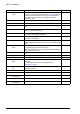
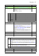
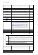

Table Of Contents
- Introduction to the manual
- Using the control panel
- Control locations and operating modes
- Program features
- What this chapter contains
- Drive configuration and programming
- Control interfaces
- Motor control
- Direct torque control (DTC)
- Reference ramping
- Constant speeds/frequencies
- Critical speeds/frequencies
- Speed controller autotune
- Oscillation damping
- Rush control
- Encoder support
- Encoder echo and emulation
- Load and motor feedback
- Position counter
- Encoder error handling
- Reading/writing position counter values through fieldbus
- Configuration of HTL encoder motor feedback
- Example 1: Using the same encoder for both load and motor feedback
- Example 2: Using two encoders
- Example 3: ACS 600 / ACS800 compatibility
- Settings
- Jogging
- Scalar motor control
- Autophasing
- Flux braking
- DC magnetization
- Application control
- DC voltage control
- Safety and protections
- Emergency stop
- Motor thermal protection
- Thermal protection of motor cable
- User load curve
- Other programmable protection functions
- External events (parameters 31.01…31.10)
- Motor phase loss detection (parameter 31.19)
- Earth (Ground) fault detection (parameter 31.20)
- Supply phase loss detection (parameter 31.21)
- Safe torque off detection (parameter 31.22)
- Swapped supply and motor cabling (parameter 31.23)
- Stall protection (parameters 31.24…31.28)
- Overspeed protection (parameter 31.30)
- Ramp stop supervision (parameters 31.32, 31.33, 31.37 and 31.38)
- Custom motor current fault limit (parameter 31.42)
- Local control loss detection (parameter 49.05)
- Automatic fault resets
- Diagnostics
- Miscellaneous
- Application macros
- Parameters
- 01 Actual values
- 03 Input references
- 04 Warnings and faults
- 05 Diagnostics
- 06 Control and status words
- 07 System info
- 10 Standard DI, RO
- 11 Standard DIO, FI, FO
- 12 Standard AI
- 13 Standard AO
- 14 I/O extension module 1
- 15 I/O extension module 2
- 16 I/O extension module 3
- 19 Operation mode
- 20 Start/stop/direction
- 21 Start/stop mode
- 22 Speed reference selection
- 23 Speed reference ramp
- 24 Speed reference conditioning
- 25 Speed control
- 26 Torque reference chain
- 28 Frequency reference chain
- 30 Limits
- 31 Fault functions
- 32 Supervision
- 33 Generic timer & counter
- 35 Motor thermal protection
- 36 Load analyzer
- 37 User load curve
- 40 Process PID set 1
- 41 Process PID set 2
- 43 Brake chopper
- 44 Mechanical brake control
- 45 Energy efficiency
- 46 Monitoring/scaling settings
- 47 Data storage
- 49 Panel port communication
- 50 Fieldbus adapter (FBA)
- 51 FBA A settings
- 52 FBA A data in
- 53 FBA A data out
- 54 FBA B settings
- 55 FBA B data in
- 56 FBA B data out
- 58 Embedded fieldbus
- 60 DDCS communication
- 61 D2D and DDCS transmit data
- 62 D2D and DDCS receive data
- 90 Feedback selection
- 91 Encoder module settings
- 92 Encoder 1 configuration
- 93 Encoder 2 configuration
- 94 LSU control
- 95 HW configuration
- 96 System
- 97 Motor control
- 98 User motor parameters
- 99 Motor data
- 200 Safety
- Additional parameter data
- Fault tracing
- Fieldbus control through the embedded fieldbus interface (EFB)
- What this chapter contains
- System overview
- Connecting the fieldbus to the drive
- Setting up the embedded fieldbus interface
- Setting the drive control parameters
- Basics of the embedded fieldbus interface
- About the control profiles
- The ABB Drives profile
- The Transparent profile
- Modbus function codes
- Exception codes
- Coils (0xxxx reference set)
- Discrete inputs (1xxxx reference set)
- Error code registers (holding registers 400090…400100)
- Fieldbus control through a fieldbus adapter
- What this chapter contains
- System overview
- Basics of the fieldbus control interface
- Setting up the drive for fieldbus control
- Control chain diagrams
- What this chapter contains
- Speed reference source selection I
- Speed reference source selection II
- Speed reference ramping and shaping
- Motor feedback configuration
- Load feedback and position counter configuration
- Speed error calculation
- Speed controller
- Torque reference source selection and modification
- Operating mode selection
- Reference selection for torque controller
- Torque limitation
- Torque controller
- Frequency reference selection
- Frequency reference modification
- Process PID setpoint and feedback source selection
- Process PID controller
- Master/Follower communication I (Master)
- Master/Follower communication II (Follower)
- Further information

Parameters 267
33
33 Generic timer &
counter
Configuration of maintenance timers/counters.
See also section Maintenance timers and counters (page 87).
33.01 Counter status Displays the maintenance timer/counter status word,
indicating which maintenance timers/counters have exceeded
their limits.
This parameter is read-only.
-
0000 0000b …
0011 1111b
Maintenance time/counter status word. 1 = 1
33.10 On-time 1 actual Displays the actual present value of on-time timer 1.
The timer runs whenever the signal selected by parameter
33.13 On-time 1 source is on.
When the timer exceeds the limit set by 33.11 On-time 1 warn
limit, bit 0 of 33.01 Counter status is set to 1. The warning
specified by 33.14 On-time 1 warn message is also given if
enabled by 33.12 On-time 1 function.
The timer can be reset from the Drive composer PC tool, or
from the control panel by keeping Reset depressed for over 3
seconds.
-
0…4294967295 s Actual present value of on-time timer 1. -
33.11 On-time 1 warn limit Sets the warning limit for on-time timer 1. 0 s
0…4294967295 s Warning limit for on-time timer 1. -
33.12 On-time 1 function Configures on-time timer 1. 0000b
0000b…0011b On-time timer 1 configuration word. 1 = 1
33.13 On-time 1 source Selects the signal to be monitored by on-time timer 1. False
False Constant 0 (timer disabled). 0
No. Name/Value Description Def/FbEq16
Bit Name Description
0 On-time1 1 = On-time timer 1 has reached its preset limit.
1 On-time2 1 = On-time timer 2 has reached its preset limit.
2 Edge 1 1 = Signal edge counter 1 has reached its preset limit.
3 Edge 2 1 = Signal edge counter 2 has reached its preset limit.
4 Value 1 1 = Value counter 1 has reached its preset limit.
5 Value 2 1 = Value counter 2 has reached its preset limit.
6…15 Reserved
Bit Function
0 Counter mode
0 = Loop: When the limit is reached, the counter is reset. The counter status (bit 0 of
33.01) switches to 1 for one second. The warning (if enabled) stays active for at least 10
seconds.
1 = Saturate: When the limit is reached, the counter status (bit 0 of 33.01) switches to 1,
and remains so until 33.10 is reset. The warning (if enabled) also stays active until 33.10
is reset.
1 Warning enable
0 = Disable: No warning is given when the limit is reached
1 = Enable: A warning (see 33.14) is given when the limit is reached
2…15 Reserved