
Firmware Manual
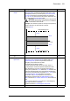

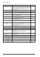
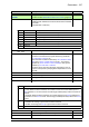
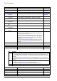
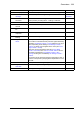

Table Of Contents
- Introduction to the manual
- Using the control panel
- Control locations and operating modes
- Program features
- What this chapter contains
- Drive configuration and programming
- Control interfaces
- Motor control
- Direct torque control (DTC)
- Reference ramping
- Constant speeds/frequencies
- Critical speeds/frequencies
- Speed controller autotune
- Oscillation damping
- Rush control
- Encoder support
- Encoder echo and emulation
- Load and motor feedback
- Position counter
- Encoder error handling
- Reading/writing position counter values through fieldbus
- Configuration of HTL encoder motor feedback
- Example 1: Using the same encoder for both load and motor feedback
- Example 2: Using two encoders
- Example 3: ACS 600 / ACS800 compatibility
- Settings
- Jogging
- Scalar motor control
- Autophasing
- Flux braking
- DC magnetization
- Application control
- DC voltage control
- Safety and protections
- Emergency stop
- Motor thermal protection
- Thermal protection of motor cable
- User load curve
- Other programmable protection functions
- External events (parameters 31.01…31.10)
- Motor phase loss detection (parameter 31.19)
- Earth (Ground) fault detection (parameter 31.20)
- Supply phase loss detection (parameter 31.21)
- Safe torque off detection (parameter 31.22)
- Swapped supply and motor cabling (parameter 31.23)
- Stall protection (parameters 31.24…31.28)
- Overspeed protection (parameter 31.30)
- Ramp stop supervision (parameters 31.32, 31.33, 31.37 and 31.38)
- Custom motor current fault limit (parameter 31.42)
- Local control loss detection (parameter 49.05)
- Automatic fault resets
- Diagnostics
- Miscellaneous
- Application macros
- Parameters
- 01 Actual values
- 03 Input references
- 04 Warnings and faults
- 05 Diagnostics
- 06 Control and status words
- 07 System info
- 10 Standard DI, RO
- 11 Standard DIO, FI, FO
- 12 Standard AI
- 13 Standard AO
- 14 I/O extension module 1
- 15 I/O extension module 2
- 16 I/O extension module 3
- 19 Operation mode
- 20 Start/stop/direction
- 21 Start/stop mode
- 22 Speed reference selection
- 23 Speed reference ramp
- 24 Speed reference conditioning
- 25 Speed control
- 26 Torque reference chain
- 28 Frequency reference chain
- 30 Limits
- 31 Fault functions
- 32 Supervision
- 33 Generic timer & counter
- 35 Motor thermal protection
- 36 Load analyzer
- 37 User load curve
- 40 Process PID set 1
- 41 Process PID set 2
- 43 Brake chopper
- 44 Mechanical brake control
- 45 Energy efficiency
- 46 Monitoring/scaling settings
- 47 Data storage
- 49 Panel port communication
- 50 Fieldbus adapter (FBA)
- 51 FBA A settings
- 52 FBA A data in
- 53 FBA A data out
- 54 FBA B settings
- 55 FBA B data in
- 56 FBA B data out
- 58 Embedded fieldbus
- 60 DDCS communication
- 61 D2D and DDCS transmit data
- 62 D2D and DDCS receive data
- 90 Feedback selection
- 91 Encoder module settings
- 92 Encoder 1 configuration
- 93 Encoder 2 configuration
- 94 LSU control
- 95 HW configuration
- 96 System
- 97 Motor control
- 98 User motor parameters
- 99 Motor data
- 200 Safety
- Additional parameter data
- Fault tracing
- Fieldbus control through the embedded fieldbus interface (EFB)
- What this chapter contains
- System overview
- Connecting the fieldbus to the drive
- Setting up the embedded fieldbus interface
- Setting the drive control parameters
- Basics of the embedded fieldbus interface
- About the control profiles
- The ABB Drives profile
- The Transparent profile
- Modbus function codes
- Exception codes
- Coils (0xxxx reference set)
- Discrete inputs (1xxxx reference set)
- Error code registers (holding registers 400090…400100)
- Fieldbus control through a fieldbus adapter
- What this chapter contains
- System overview
- Basics of the fieldbus control interface
- Setting up the drive for fieldbus control
- Control chain diagrams
- What this chapter contains
- Speed reference source selection I
- Speed reference source selection II
- Speed reference ramping and shaping
- Motor feedback configuration
- Load feedback and position counter configuration
- Speed error calculation
- Speed controller
- Torque reference source selection and modification
- Operating mode selection
- Reference selection for torque controller
- Torque limitation
- Torque controller
- Frequency reference selection
- Frequency reference modification
- Process PID setpoint and feedback source selection
- Process PID controller
- Master/Follower communication I (Master)
- Master/Follower communication II (Follower)
- Further information

270 Parameters
33.32 Edge counter 1
function
Configures signal edge counter 1. 0000b
0000b…1111b Edge counter 1 configuration word. 1 = 1
33.33 Edge counter 1
source
Selects the signal to be monitored by signal edge counter 1. False
False Constant 0. 0
True Constant 1. 1
RO1 Bit 0 of 10.21 RO status (page 144). 2
Other [bit] Source selection (see Terms and abbreviations on page 112). -
33.34 Edge counter 1
divider
Defines a divisor for signal edge counter 1. Determines how
many signal edges increment the counter by 1.
1
1…4294967295 Divisor for signal edge counter 1. -
33.35 Edge counter 1
warn message
Selects the optional warning message for signal edge counter
1.
Edge counter
1 exceeded
Edge counter 1
exceeded
A888 Edge counter 1. The message text can be edited on the
control panel by choosing Menu – Settings – Edit texts.
2
Counted main
contactor
A884 Main contactor.11
Counted output
relay
A881 Output relay.12
Counted motor
starts
A882 Motor starts.13
Counted power ups A883 Power ups.14
Counted DC
charges
A885 DC charge.15
No. Name/Value Description Def/FbEq16
Bit Function
0 Counter mode
0 = Loop: When the limit is reached, the counter is reset. The counter status (bit 2 of
33.01) switches to 1 and remains so until the counter is again incremented. The warning
(if enabled) stays active for at least 10 seconds.
1 = Saturate: When the limit is reached, the counter status (bit 2 of 33.01) switches to 1,
and remains so until 33.30 is reset. The warning (if enabled) also stays active until 33.30
is reset.
1 Warning enable
0 = Disable: No warning is given when the limit is reached
1 = Enable: A warning (see 33.35) is given when the limit is reached
2 Count rising edges
0 = Disable: Rising edges are not counted
1 = Enable: Rising edges are counted
3 Count falling edges
0 = Disable: Falling edges are not counted
1 = Enable: Falling edges are counted
4…15 Reserved