
Firmware Manual

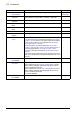


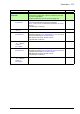
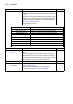


Table Of Contents
- Introduction to the manual
- Using the control panel
- Control locations and operating modes
- Program features
- What this chapter contains
- Drive configuration and programming
- Control interfaces
- Motor control
- Direct torque control (DTC)
- Reference ramping
- Constant speeds/frequencies
- Critical speeds/frequencies
- Speed controller autotune
- Oscillation damping
- Rush control
- Encoder support
- Encoder echo and emulation
- Load and motor feedback
- Position counter
- Encoder error handling
- Reading/writing position counter values through fieldbus
- Configuration of HTL encoder motor feedback
- Example 1: Using the same encoder for both load and motor feedback
- Example 2: Using two encoders
- Example 3: ACS 600 / ACS800 compatibility
- Settings
- Jogging
- Scalar motor control
- Autophasing
- Flux braking
- DC magnetization
- Application control
- DC voltage control
- Safety and protections
- Emergency stop
- Motor thermal protection
- Thermal protection of motor cable
- User load curve
- Other programmable protection functions
- External events (parameters 31.01…31.10)
- Motor phase loss detection (parameter 31.19)
- Earth (Ground) fault detection (parameter 31.20)
- Supply phase loss detection (parameter 31.21)
- Safe torque off detection (parameter 31.22)
- Swapped supply and motor cabling (parameter 31.23)
- Stall protection (parameters 31.24…31.28)
- Overspeed protection (parameter 31.30)
- Ramp stop supervision (parameters 31.32, 31.33, 31.37 and 31.38)
- Custom motor current fault limit (parameter 31.42)
- Local control loss detection (parameter 49.05)
- Automatic fault resets
- Diagnostics
- Miscellaneous
- Application macros
- Parameters
- 01 Actual values
- 03 Input references
- 04 Warnings and faults
- 05 Diagnostics
- 06 Control and status words
- 07 System info
- 10 Standard DI, RO
- 11 Standard DIO, FI, FO
- 12 Standard AI
- 13 Standard AO
- 14 I/O extension module 1
- 15 I/O extension module 2
- 16 I/O extension module 3
- 19 Operation mode
- 20 Start/stop/direction
- 21 Start/stop mode
- 22 Speed reference selection
- 23 Speed reference ramp
- 24 Speed reference conditioning
- 25 Speed control
- 26 Torque reference chain
- 28 Frequency reference chain
- 30 Limits
- 31 Fault functions
- 32 Supervision
- 33 Generic timer & counter
- 35 Motor thermal protection
- 36 Load analyzer
- 37 User load curve
- 40 Process PID set 1
- 41 Process PID set 2
- 43 Brake chopper
- 44 Mechanical brake control
- 45 Energy efficiency
- 46 Monitoring/scaling settings
- 47 Data storage
- 49 Panel port communication
- 50 Fieldbus adapter (FBA)
- 51 FBA A settings
- 52 FBA A data in
- 53 FBA A data out
- 54 FBA B settings
- 55 FBA B data in
- 56 FBA B data out
- 58 Embedded fieldbus
- 60 DDCS communication
- 61 D2D and DDCS transmit data
- 62 D2D and DDCS receive data
- 90 Feedback selection
- 91 Encoder module settings
- 92 Encoder 1 configuration
- 93 Encoder 2 configuration
- 94 LSU control
- 95 HW configuration
- 96 System
- 97 Motor control
- 98 User motor parameters
- 99 Motor data
- 200 Safety
- Additional parameter data
- Fault tracing
- Fieldbus control through the embedded fieldbus interface (EFB)
- What this chapter contains
- System overview
- Connecting the fieldbus to the drive
- Setting up the embedded fieldbus interface
- Setting the drive control parameters
- Basics of the embedded fieldbus interface
- About the control profiles
- The ABB Drives profile
- The Transparent profile
- Modbus function codes
- Exception codes
- Coils (0xxxx reference set)
- Discrete inputs (1xxxx reference set)
- Error code registers (holding registers 400090…400100)
- Fieldbus control through a fieldbus adapter
- What this chapter contains
- System overview
- Basics of the fieldbus control interface
- Setting up the drive for fieldbus control
- Control chain diagrams
- What this chapter contains
- Speed reference source selection I
- Speed reference source selection II
- Speed reference ramping and shaping
- Motor feedback configuration
- Load feedback and position counter configuration
- Speed error calculation
- Speed controller
- Torque reference source selection and modification
- Operating mode selection
- Reference selection for torque controller
- Torque limitation
- Torque controller
- Frequency reference selection
- Frequency reference modification
- Process PID setpoint and feedback source selection
- Process PID controller
- Master/Follower communication I (Master)
- Master/Follower communication II (Follower)
- Further information

Parameters 279
35.21 Temperature 2
source
Selects the source from which measured temperature 2 is
read.
For wiring examples, see the hardware manual of the drive.
Usually this source is from a sensor connected to the motor
controlled by the drive, but it could be used to measure and
monitor a temperature from other parts of the process as long
as a suitable sensor is used as per the selection list.
Disabled
Disabled None. Temperature monitoring function 2 is disabled. 0
Estimated
temperature
Estimated motor temperature (see parameter 35.01 Motor
estimated temperature).
The temperature is estimated from an internal drive
calculation. It is important to set up the ambient temperature
of the motor in 35.50 Motor ambient temperature.
1
KTY84 analog I/O KTY84 sensor connected to the analog input selected by
parameter 35.24 Temperature 2 AI source and an analog
output. The input and output can be on the drive control unit
or on an extension module.
The following settings are required:
• Set the hardware jumper or switch related to the analog
input to U (voltage). Any change must be validated by a
control unit reboot.
• Set the unit selection parameter of the input to volt.
• Set the source selection parameter of the analog output to
“Force KTY84 excitation”.
• Select the analog input in parameter 35.24. In case the
input is located on an I/O extension module, use the
selection Other to point at the actual input value parameter
(for example, 14.26 AI1 actual value).
The analog output feeds a constant current through the
sensor. As the resistance of the sensor changes along with its
temperature, the voltage over the sensor changes. The
voltage is read by the analog input and converted into
degrees.
2
KTY84 encoder
module 1
KTY84 sensor connected to encoder interface 1.
See also parameters 91.21 Module 1 temp sensor type and
91.22 Module 1 temp filter time.
3
KTY84 encoder
module 2
KTY84 sensor connected to encoder interface 2.
See also parameters 91.24 Module 2 temp sensor type and
91.25 Module 2 temp filter time.
4
1 × Pt100 analog
I/O
Pt100 sensor connected to a standard analog input selected
by parameter 35.24 Temperature 2 AI source and an analog
output. The input and output can be on the drive control unit
or on an extension module.
The required settings are the same as with selection KTY84
analog I/O, except that the source selection parameter of the
analog output must be set to Force Pt100 excitation.
5
2 × Pt100 analog
I/O
As selection
1 × Pt100 analog I/O, but with two sensors
connected in series. Using multiple sensors improves
measurement accuracy significantly.
6
3 × Pt100 analog
I/O
As selection 1 × Pt100 analog I/O, but with three sensors
connected in series. Using multiple sensors improves
measurement accuracy significantly.
7
No. Name/Value Description Def/FbEq16