
Firmware Manual
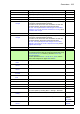
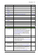

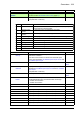

Table Of Contents
- Introduction to the manual
- Using the control panel
- Control locations and operating modes
- Program features
- What this chapter contains
- Drive configuration and programming
- Control interfaces
- Motor control
- Direct torque control (DTC)
- Reference ramping
- Constant speeds/frequencies
- Critical speeds/frequencies
- Speed controller autotune
- Oscillation damping
- Rush control
- Encoder support
- Encoder echo and emulation
- Load and motor feedback
- Position counter
- Encoder error handling
- Reading/writing position counter values through fieldbus
- Configuration of HTL encoder motor feedback
- Example 1: Using the same encoder for both load and motor feedback
- Example 2: Using two encoders
- Example 3: ACS 600 / ACS800 compatibility
- Settings
- Jogging
- Scalar motor control
- Autophasing
- Flux braking
- DC magnetization
- Application control
- DC voltage control
- Safety and protections
- Emergency stop
- Motor thermal protection
- Thermal protection of motor cable
- User load curve
- Other programmable protection functions
- External events (parameters 31.01…31.10)
- Motor phase loss detection (parameter 31.19)
- Earth (Ground) fault detection (parameter 31.20)
- Supply phase loss detection (parameter 31.21)
- Safe torque off detection (parameter 31.22)
- Swapped supply and motor cabling (parameter 31.23)
- Stall protection (parameters 31.24…31.28)
- Overspeed protection (parameter 31.30)
- Ramp stop supervision (parameters 31.32, 31.33, 31.37 and 31.38)
- Custom motor current fault limit (parameter 31.42)
- Local control loss detection (parameter 49.05)
- Automatic fault resets
- Diagnostics
- Miscellaneous
- Application macros
- Parameters
- 01 Actual values
- 03 Input references
- 04 Warnings and faults
- 05 Diagnostics
- 06 Control and status words
- 07 System info
- 10 Standard DI, RO
- 11 Standard DIO, FI, FO
- 12 Standard AI
- 13 Standard AO
- 14 I/O extension module 1
- 15 I/O extension module 2
- 16 I/O extension module 3
- 19 Operation mode
- 20 Start/stop/direction
- 21 Start/stop mode
- 22 Speed reference selection
- 23 Speed reference ramp
- 24 Speed reference conditioning
- 25 Speed control
- 26 Torque reference chain
- 28 Frequency reference chain
- 30 Limits
- 31 Fault functions
- 32 Supervision
- 33 Generic timer & counter
- 35 Motor thermal protection
- 36 Load analyzer
- 37 User load curve
- 40 Process PID set 1
- 41 Process PID set 2
- 43 Brake chopper
- 44 Mechanical brake control
- 45 Energy efficiency
- 46 Monitoring/scaling settings
- 47 Data storage
- 49 Panel port communication
- 50 Fieldbus adapter (FBA)
- 51 FBA A settings
- 52 FBA A data in
- 53 FBA A data out
- 54 FBA B settings
- 55 FBA B data in
- 56 FBA B data out
- 58 Embedded fieldbus
- 60 DDCS communication
- 61 D2D and DDCS transmit data
- 62 D2D and DDCS receive data
- 90 Feedback selection
- 91 Encoder module settings
- 92 Encoder 1 configuration
- 93 Encoder 2 configuration
- 94 LSU control
- 95 HW configuration
- 96 System
- 97 Motor control
- 98 User motor parameters
- 99 Motor data
- 200 Safety
- Additional parameter data
- Fault tracing
- Fieldbus control through the embedded fieldbus interface (EFB)
- What this chapter contains
- System overview
- Connecting the fieldbus to the drive
- Setting up the embedded fieldbus interface
- Setting the drive control parameters
- Basics of the embedded fieldbus interface
- About the control profiles
- The ABB Drives profile
- The Transparent profile
- Modbus function codes
- Exception codes
- Coils (0xxxx reference set)
- Discrete inputs (1xxxx reference set)
- Error code registers (holding registers 400090…400100)
- Fieldbus control through a fieldbus adapter
- What this chapter contains
- System overview
- Basics of the fieldbus control interface
- Setting up the drive for fieldbus control
- Control chain diagrams
- What this chapter contains
- Speed reference source selection I
- Speed reference source selection II
- Speed reference ramping and shaping
- Motor feedback configuration
- Load feedback and position counter configuration
- Speed error calculation
- Speed controller
- Torque reference source selection and modification
- Operating mode selection
- Reference selection for torque controller
- Torque limitation
- Torque controller
- Frequency reference selection
- Frequency reference modification
- Process PID setpoint and feedback source selection
- Process PID controller
- Master/Follower communication I (Master)
- Master/Follower communication II (Follower)
- Further information

Parameters 307
41.44 Set 2 sleep delay See parameter 40.44 Set 1 sleep delay. 60.0 s
41.45 Set 2 sleep boost
time
See parameter 40.45 Set 1 sleep boost time. 0.0 s
41.46 Set 2 sleep boost
step
See parameter 40.46 Set 1 sleep boost step.0.0
41.47 Set 2 wake-up
deviation
See parameter 40.47 Set 1 wake-up deviation.0.00 rpm, %
or Hz
41.48 Set 2 wake-up
delay
See parameter 40.48 Set 1 wake-up delay.0.50 s
41.49 Set 2 tracking mode See parameter 40.49 Set 1 tracking mode. Not selected
41.50 Set 2 tracking ref
selection
See parameter 40.50 Set 1 tracking ref selection. Not selected
41.51 Set 2 trim mode See parameter 40.51 Set 1 trim mode. Off
41.52 Set 2 trim selection See parameter 40.52 Set 1 trim selection. Torque
41.53 Set 2 trimmed ref
pointer
See parameter 40.53 Set 1 trimmed ref pointer. Not selected
41.54 Set 2 trim mix See parameter 40.54 Set 1 trim mix.0.000
41.55 Set 2 trim adjust See parameter 40.55 Set 1 trim adjust.1.000
41.56 Set 2 trim source See parameter 40.56 Set 1 trim source. PID ref
41.60 Set 2 PID activation
source
See parameter 40.60 Set 1 PID activation source. On
43
43 Brake chopper
Settings for the internal brake chopper.
43.01 Braking resistor
temperature
Displays the estimated temperature of the brake resistor, or
how close the brake resistor is to being too hot.
The value is given in percent where 100% is the temperature
the resistor would reach if the maximum continuous braking
power (43.09 Brake resistor Pmax cont) is applied to the
resistor for 100% rated time. The thermal time constant
(43.08 Brake resistor thermal tc) defines the rated time to
achieve 63% temperature. 100% would be reached when
100% time has elapsed.
This parameter is read-only.
-
0.0 … 120.0% Estimated brake resistor temperature. 1 = 1%
43.06 Brake chopper
function
Enables brake chopper control.
Note: Before enabling brake chopper control, ensure that
• a brake resistor is connected, and
• the supply voltage range (parameter 95.01 Supply voltage)
has been selected correctly.
Disabled
Disabled Brake chopper control disabled. 0
Enabled with
thermal model
Brake chopper control enabled with resistor overload
protection.
Note: Before using this setting, ensure that overvoltage
control is switched off (parameter 30.30 Overvoltage control).
1
Enabled without
thermal model
Brake chopper control enabled without resistor overload
protection. This setting can be used, for example, if the
resistor is equipped with a thermal circuit breaker that is wired
to stop the drive if the resistor overheats.
Before using this setting, ensure that overvoltage control is
switched off (parameter 30.30 Overvoltage control)
2
No. Name/Value Description Def/FbEq16