
Firmware Manual


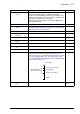
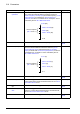
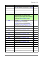
Table Of Contents
- Introduction to the manual
- Using the control panel
- Control locations and operating modes
- Program features
- What this chapter contains
- Drive configuration and programming
- Control interfaces
- Motor control
- Direct torque control (DTC)
- Reference ramping
- Constant speeds/frequencies
- Critical speeds/frequencies
- Speed controller autotune
- Oscillation damping
- Rush control
- Encoder support
- Encoder echo and emulation
- Load and motor feedback
- Position counter
- Encoder error handling
- Reading/writing position counter values through fieldbus
- Configuration of HTL encoder motor feedback
- Example 1: Using the same encoder for both load and motor feedback
- Example 2: Using two encoders
- Example 3: ACS 600 / ACS800 compatibility
- Settings
- Jogging
- Scalar motor control
- Autophasing
- Flux braking
- DC magnetization
- Application control
- DC voltage control
- Safety and protections
- Emergency stop
- Motor thermal protection
- Thermal protection of motor cable
- User load curve
- Other programmable protection functions
- External events (parameters 31.01…31.10)
- Motor phase loss detection (parameter 31.19)
- Earth (Ground) fault detection (parameter 31.20)
- Supply phase loss detection (parameter 31.21)
- Safe torque off detection (parameter 31.22)
- Swapped supply and motor cabling (parameter 31.23)
- Stall protection (parameters 31.24…31.28)
- Overspeed protection (parameter 31.30)
- Ramp stop supervision (parameters 31.32, 31.33, 31.37 and 31.38)
- Custom motor current fault limit (parameter 31.42)
- Local control loss detection (parameter 49.05)
- Automatic fault resets
- Diagnostics
- Miscellaneous
- Application macros
- Parameters
- 01 Actual values
- 03 Input references
- 04 Warnings and faults
- 05 Diagnostics
- 06 Control and status words
- 07 System info
- 10 Standard DI, RO
- 11 Standard DIO, FI, FO
- 12 Standard AI
- 13 Standard AO
- 14 I/O extension module 1
- 15 I/O extension module 2
- 16 I/O extension module 3
- 19 Operation mode
- 20 Start/stop/direction
- 21 Start/stop mode
- 22 Speed reference selection
- 23 Speed reference ramp
- 24 Speed reference conditioning
- 25 Speed control
- 26 Torque reference chain
- 28 Frequency reference chain
- 30 Limits
- 31 Fault functions
- 32 Supervision
- 33 Generic timer & counter
- 35 Motor thermal protection
- 36 Load analyzer
- 37 User load curve
- 40 Process PID set 1
- 41 Process PID set 2
- 43 Brake chopper
- 44 Mechanical brake control
- 45 Energy efficiency
- 46 Monitoring/scaling settings
- 47 Data storage
- 49 Panel port communication
- 50 Fieldbus adapter (FBA)
- 51 FBA A settings
- 52 FBA A data in
- 53 FBA A data out
- 54 FBA B settings
- 55 FBA B data in
- 56 FBA B data out
- 58 Embedded fieldbus
- 60 DDCS communication
- 61 D2D and DDCS transmit data
- 62 D2D and DDCS receive data
- 90 Feedback selection
- 91 Encoder module settings
- 92 Encoder 1 configuration
- 93 Encoder 2 configuration
- 94 LSU control
- 95 HW configuration
- 96 System
- 97 Motor control
- 98 User motor parameters
- 99 Motor data
- 200 Safety
- Additional parameter data
- Fault tracing
- Fieldbus control through the embedded fieldbus interface (EFB)
- What this chapter contains
- System overview
- Connecting the fieldbus to the drive
- Setting up the embedded fieldbus interface
- Setting the drive control parameters
- Basics of the embedded fieldbus interface
- About the control profiles
- The ABB Drives profile
- The Transparent profile
- Modbus function codes
- Exception codes
- Coils (0xxxx reference set)
- Discrete inputs (1xxxx reference set)
- Error code registers (holding registers 400090…400100)
- Fieldbus control through a fieldbus adapter
- What this chapter contains
- System overview
- Basics of the fieldbus control interface
- Setting up the drive for fieldbus control
- Control chain diagrams
- What this chapter contains
- Speed reference source selection I
- Speed reference source selection II
- Speed reference ramping and shaping
- Motor feedback configuration
- Load feedback and position counter configuration
- Speed error calculation
- Speed controller
- Torque reference source selection and modification
- Operating mode selection
- Reference selection for torque controller
- Torque limitation
- Torque controller
- Frequency reference selection
- Frequency reference modification
- Process PID setpoint and feedback source selection
- Process PID controller
- Master/Follower communication I (Master)
- Master/Follower communication II (Follower)
- Further information

314 Parameters
45.06 Saved money Displays the monetary savings compared to direct-on-line
motor connection. This value is a calculated by multiplying
the saved energy in kWh by the currently active energy tariff
(45.14 Tariff selection).
When this parameter rolls over, parameter 45.05 Saved
money x1000 is incremented.
The currency is defined by parameter 45.17 Tariff currency
unit.
This parameter is read-only (see parameter 45.21 Energy
calculations reset).
-
0.00 … 999.99 units Monetary savings. 1 = 1 unit
45.08 CO2 reduction in
kilotons
Displays the reduction in CO
2
emissions in metric kilotons
compared to direct-on-line motor connection. This value is
incremented when parameter 45.09 CO2 reduction in tons
rolls over.
This parameter is read-only (see parameter 45.21 Energy
calculations reset).
-
0…65535 metric
kilotons
Reduction in CO
2
emissions in metric kilotons. 1 = 1 metric
kiloton
45.09 CO2 reduction in
tons
Displays the reduction in CO
2
emissions in metric tons
compared to direct-on-line motor connection. This value is
calculated by multiplying the saved energy in MWh by the
value of parameter 45.18 CO2 conversion factor (by default,
0.5 metric tons/MWh).
When this parameter rolls over, parameter 45.08 CO2
reduction in kilotons is incremented.
This parameter is read-only (see parameter 45.21 Energy
calculations reset).
-
0.0 … 999.9 metric
tons
Reduction in CO
2
emissions in metric tons. 1 = 1 metric
ton
45.11 Energy optimizer Enables/disables the energy optimization function. The
function optimizes the motor flux so that total energy
consumption and motor noise level are reduced when the
drive operates below the nominal load. The total efficiency
(motor and drive) can be improved by 1…20% depending on
load torque and speed.
Note: With a permanent magnet motor or a synchronous
reluctance motor, energy optimization is always enabled
regardless of this parameter.
Disable
Disable Energy optimization disabled. 0
Enable Energy optimization enabled. 1
45.12 Energy tariff 1 Defines energy tariff 1 (price of energy per kWh). Depending
on the setting of parameter 45.14 Tariff selection, either this
value or 45.13 Energy tariff 2 is used for reference when
monetary savings are calculated.
The currency is defined by parameter 45.17 Tariff currency
unit.
Note: Tariffs are read only at the instant of selection, and are
not applied retroactively.
1.000 units
0.000 …
4294967.295 units
Energy tariff 1. -
No. Name/Value Description Def/FbEq16