
Firmware Manual
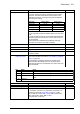
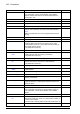
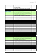


Table Of Contents
- Introduction to the manual
- Using the control panel
- Control locations and operating modes
- Program features
- What this chapter contains
- Drive configuration and programming
- Control interfaces
- Motor control
- Direct torque control (DTC)
- Reference ramping
- Constant speeds/frequencies
- Critical speeds/frequencies
- Speed controller autotune
- Oscillation damping
- Rush control
- Encoder support
- Encoder echo and emulation
- Load and motor feedback
- Position counter
- Encoder error handling
- Reading/writing position counter values through fieldbus
- Configuration of HTL encoder motor feedback
- Example 1: Using the same encoder for both load and motor feedback
- Example 2: Using two encoders
- Example 3: ACS 600 / ACS800 compatibility
- Settings
- Jogging
- Scalar motor control
- Autophasing
- Flux braking
- DC magnetization
- Application control
- DC voltage control
- Safety and protections
- Emergency stop
- Motor thermal protection
- Thermal protection of motor cable
- User load curve
- Other programmable protection functions
- External events (parameters 31.01…31.10)
- Motor phase loss detection (parameter 31.19)
- Earth (Ground) fault detection (parameter 31.20)
- Supply phase loss detection (parameter 31.21)
- Safe torque off detection (parameter 31.22)
- Swapped supply and motor cabling (parameter 31.23)
- Stall protection (parameters 31.24…31.28)
- Overspeed protection (parameter 31.30)
- Ramp stop supervision (parameters 31.32, 31.33, 31.37 and 31.38)
- Custom motor current fault limit (parameter 31.42)
- Local control loss detection (parameter 49.05)
- Automatic fault resets
- Diagnostics
- Miscellaneous
- Application macros
- Parameters
- 01 Actual values
- 03 Input references
- 04 Warnings and faults
- 05 Diagnostics
- 06 Control and status words
- 07 System info
- 10 Standard DI, RO
- 11 Standard DIO, FI, FO
- 12 Standard AI
- 13 Standard AO
- 14 I/O extension module 1
- 15 I/O extension module 2
- 16 I/O extension module 3
- 19 Operation mode
- 20 Start/stop/direction
- 21 Start/stop mode
- 22 Speed reference selection
- 23 Speed reference ramp
- 24 Speed reference conditioning
- 25 Speed control
- 26 Torque reference chain
- 28 Frequency reference chain
- 30 Limits
- 31 Fault functions
- 32 Supervision
- 33 Generic timer & counter
- 35 Motor thermal protection
- 36 Load analyzer
- 37 User load curve
- 40 Process PID set 1
- 41 Process PID set 2
- 43 Brake chopper
- 44 Mechanical brake control
- 45 Energy efficiency
- 46 Monitoring/scaling settings
- 47 Data storage
- 49 Panel port communication
- 50 Fieldbus adapter (FBA)
- 51 FBA A settings
- 52 FBA A data in
- 53 FBA A data out
- 54 FBA B settings
- 55 FBA B data in
- 56 FBA B data out
- 58 Embedded fieldbus
- 60 DDCS communication
- 61 D2D and DDCS transmit data
- 62 D2D and DDCS receive data
- 90 Feedback selection
- 91 Encoder module settings
- 92 Encoder 1 configuration
- 93 Encoder 2 configuration
- 94 LSU control
- 95 HW configuration
- 96 System
- 97 Motor control
- 98 User motor parameters
- 99 Motor data
- 200 Safety
- Additional parameter data
- Fault tracing
- Fieldbus control through the embedded fieldbus interface (EFB)
- What this chapter contains
- System overview
- Connecting the fieldbus to the drive
- Setting up the embedded fieldbus interface
- Setting the drive control parameters
- Basics of the embedded fieldbus interface
- About the control profiles
- The ABB Drives profile
- The Transparent profile
- Modbus function codes
- Exception codes
- Coils (0xxxx reference set)
- Discrete inputs (1xxxx reference set)
- Error code registers (holding registers 400090…400100)
- Fieldbus control through a fieldbus adapter
- What this chapter contains
- System overview
- Basics of the fieldbus control interface
- Setting up the drive for fieldbus control
- Control chain diagrams
- What this chapter contains
- Speed reference source selection I
- Speed reference source selection II
- Speed reference ramping and shaping
- Motor feedback configuration
- Load feedback and position counter configuration
- Speed error calculation
- Speed controller
- Torque reference source selection and modification
- Operating mode selection
- Reference selection for torque controller
- Torque limitation
- Torque controller
- Frequency reference selection
- Frequency reference modification
- Process PID setpoint and feedback source selection
- Process PID controller
- Master/Follower communication I (Master)
- Master/Follower communication II (Follower)
- Further information

338 Parameters
58.10 All packets Displays a count of valid packets addressed to any device on
the bus. During normal operation, this number increases
constantly.
Can be reset from the control panel by keeping Reset
depressed for over 3 seconds.
-
0…4294967295 Number of all received packets. 1 = 1
58.11 UART errors Displays a count of character errors received by the drive. An
increasing count indicates a configuration problem on the
bus.
Can be reset from the control panel by keeping Reset
depressed for over 3 seconds.
-
0…4294967295 Number of UART errors. 1 = 1
58.12 CRC errors Displays a count of packets with a CRC error received by the
drive. An increasing count indicates interference on the bus.
Can be reset from the control panel by keeping Reset
depressed for over 3 seconds.
-
0…4294967295 Number of CRC errors. 1 = 1
58.14 Communication
loss action
Selects how the drive reacts to an EFB communication break.
Changes to this parameter take effect after the control unit is
rebooted or the new settings validated by parameter 58.06
Communication control.
See also parameters 58.15 Communication loss mode and
58.16 Communication loss time.
Fault
No No action taken (monitoring disabled). 0
Fault Drive trips on 6681 EFB comm loss. This only occurs if
control is expected from the EFB (EFB selected as source of
start/stop in the currently active location).
1
Last speed Drive generates an A7CE EFB comm loss warning and
freezes the speed to the level the drive was operating at. This
only occurs if control is expected from the EFB.
The speed is determined on the basis of actual speed using
850 ms low-pass filtering.
WARNING! Make sure that it is safe to continue
operation in case of a communication break.
2
Speed ref safe Drive generates an A7CE EFB comm loss warning and sets
the speed to the speed defined by parameter 22.41 Speed ref
safe (or 28.41 Frequency ref safe when frequency reference
is being used). This only occurs if control is expected from the
EFB.
WARNING! Make sure that it is safe to continue
operation in case of a communication break.
3
Fault always Drive trips on 6681 EFB comm loss. This occurs even though
no control is expected from the EFB.
4
Warning Drive generates an A7CE EFB comm loss warning. This
occurs even though no control is expected from the EFB.
WARNING! Make sure that it is safe to continue
operation in case of a communication break.
5
No. Name/Value Description Def/FbEq16