
Firmware Manual
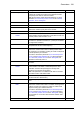


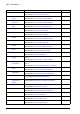


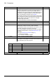
Table Of Contents
- Introduction to the manual
- Using the control panel
- Control locations and operating modes
- Program features
- What this chapter contains
- Drive configuration and programming
- Control interfaces
- Motor control
- Direct torque control (DTC)
- Reference ramping
- Constant speeds/frequencies
- Critical speeds/frequencies
- Speed controller autotune
- Oscillation damping
- Rush control
- Encoder support
- Encoder echo and emulation
- Load and motor feedback
- Position counter
- Encoder error handling
- Reading/writing position counter values through fieldbus
- Configuration of HTL encoder motor feedback
- Example 1: Using the same encoder for both load and motor feedback
- Example 2: Using two encoders
- Example 3: ACS 600 / ACS800 compatibility
- Settings
- Jogging
- Scalar motor control
- Autophasing
- Flux braking
- DC magnetization
- Application control
- DC voltage control
- Safety and protections
- Emergency stop
- Motor thermal protection
- Thermal protection of motor cable
- User load curve
- Other programmable protection functions
- External events (parameters 31.01…31.10)
- Motor phase loss detection (parameter 31.19)
- Earth (Ground) fault detection (parameter 31.20)
- Supply phase loss detection (parameter 31.21)
- Safe torque off detection (parameter 31.22)
- Swapped supply and motor cabling (parameter 31.23)
- Stall protection (parameters 31.24…31.28)
- Overspeed protection (parameter 31.30)
- Ramp stop supervision (parameters 31.32, 31.33, 31.37 and 31.38)
- Custom motor current fault limit (parameter 31.42)
- Local control loss detection (parameter 49.05)
- Automatic fault resets
- Diagnostics
- Miscellaneous
- Application macros
- Parameters
- 01 Actual values
- 03 Input references
- 04 Warnings and faults
- 05 Diagnostics
- 06 Control and status words
- 07 System info
- 10 Standard DI, RO
- 11 Standard DIO, FI, FO
- 12 Standard AI
- 13 Standard AO
- 14 I/O extension module 1
- 15 I/O extension module 2
- 16 I/O extension module 3
- 19 Operation mode
- 20 Start/stop/direction
- 21 Start/stop mode
- 22 Speed reference selection
- 23 Speed reference ramp
- 24 Speed reference conditioning
- 25 Speed control
- 26 Torque reference chain
- 28 Frequency reference chain
- 30 Limits
- 31 Fault functions
- 32 Supervision
- 33 Generic timer & counter
- 35 Motor thermal protection
- 36 Load analyzer
- 37 User load curve
- 40 Process PID set 1
- 41 Process PID set 2
- 43 Brake chopper
- 44 Mechanical brake control
- 45 Energy efficiency
- 46 Monitoring/scaling settings
- 47 Data storage
- 49 Panel port communication
- 50 Fieldbus adapter (FBA)
- 51 FBA A settings
- 52 FBA A data in
- 53 FBA A data out
- 54 FBA B settings
- 55 FBA B data in
- 56 FBA B data out
- 58 Embedded fieldbus
- 60 DDCS communication
- 61 D2D and DDCS transmit data
- 62 D2D and DDCS receive data
- 90 Feedback selection
- 91 Encoder module settings
- 92 Encoder 1 configuration
- 93 Encoder 2 configuration
- 94 LSU control
- 95 HW configuration
- 96 System
- 97 Motor control
- 98 User motor parameters
- 99 Motor data
- 200 Safety
- Additional parameter data
- Fault tracing
- Fieldbus control through the embedded fieldbus interface (EFB)
- What this chapter contains
- System overview
- Connecting the fieldbus to the drive
- Setting up the embedded fieldbus interface
- Setting the drive control parameters
- Basics of the embedded fieldbus interface
- About the control profiles
- The ABB Drives profile
- The Transparent profile
- Modbus function codes
- Exception codes
- Coils (0xxxx reference set)
- Discrete inputs (1xxxx reference set)
- Error code registers (holding registers 400090…400100)
- Fieldbus control through a fieldbus adapter
- What this chapter contains
- System overview
- Basics of the fieldbus control interface
- Setting up the drive for fieldbus control
- Control chain diagrams
- What this chapter contains
- Speed reference source selection I
- Speed reference source selection II
- Speed reference ramping and shaping
- Motor feedback configuration
- Load feedback and position counter configuration
- Speed error calculation
- Speed controller
- Torque reference source selection and modification
- Operating mode selection
- Reference selection for torque controller
- Torque limitation
- Torque controller
- Frequency reference selection
- Frequency reference modification
- Process PID setpoint and feedback source selection
- Process PID controller
- Master/Follower communication I (Master)
- Master/Follower communication II (Follower)
- Further information

382 Parameters
92.15 Transient filter (Visible when a TTL, TTL+ or HTL encoder is selected)
Activates transient filtering for the encoder (changes in
direction of rotation are ignored above the selected pulse
frequency).
4880 Hz
4880 Hz Change in direction of rotation allowed below 4880 Hz. 0
2440 Hz Change in direction of rotation allowed below 2440 Hz. 1
1220 Hz Change in direction of rotation allowed below 1220 Hz. 2
Disabled Change in direction of rotation allowed at any pulse
frequency.
3
92.16 Encoder 1 supply
voltage
(Visible when parameter 92.01 Encoder 1 type = HTL 1 or
HTL 2)
Selects the power supply voltage for encoder 1.
0V
0V Disabled. 0
5V 5 V. 1
24V 24 V. 2
92.17 Accepted pulse freq
of encoder 1
(Visible when parameter 92.01 Encoder 1 type = HTL 1 or
HTL 2)
Defines the maximum pulse frequency of encoder 1.
0 kHz
0…300 kHz Pulse frequency. 1 = 1 kHz
92.21 Encoder cable fault
mode
(Visible when a TTL, TTL+ or HTL encoder is selected)
Selects which encoder cable channels and wires are
monitored for wiring faults.
A, B
A, B A and B. 0
A, B, Z A, B and Z. 1
A+, A-, B+, B- A+, A-, B+ and B-. 2
A+, A-, B+, B-, Z+,
Z-
A+, A-, B+, B-, Z+ and Z-. 3
92.23 Maximum pulse
waiting time
(Visible when parameter 92.01 Encoder 1 type = TTL or HTL)
Determines a pulse waiting time used in speed calculation for
the encoder interface. If no pulse edges are detected within
this time, the measured speed is zeroed by the interface.
Increasing the setting can improve measuring performance
especially at low, near zero speeds.
Notes:
• The parameter is only supported by FEN-xx modules with
FPGA version VIEx 2000 or later. On older modules, the
pulse waiting time is fixed to 4 ms.
• The parameter only affects speed measurement. Position
is updated whenever a new pulse edge is detected. When
the measured speed from the interface is zero, the drive
updates its speed data based on position changes.
4 ms
1…200 ms Maximum pulse waiting time. 1 = 1 ms
No. Name/Value Description Def/FbEq16