
Firmware Manual


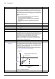


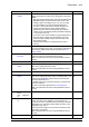

Table Of Contents
- Introduction to the manual
- Using the control panel
- Control locations and operating modes
- Program features
- What this chapter contains
- Drive configuration and programming
- Control interfaces
- Motor control
- Direct torque control (DTC)
- Reference ramping
- Constant speeds/frequencies
- Critical speeds/frequencies
- Speed controller autotune
- Oscillation damping
- Rush control
- Encoder support
- Encoder echo and emulation
- Load and motor feedback
- Position counter
- Encoder error handling
- Reading/writing position counter values through fieldbus
- Configuration of HTL encoder motor feedback
- Example 1: Using the same encoder for both load and motor feedback
- Example 2: Using two encoders
- Example 3: ACS 600 / ACS800 compatibility
- Settings
- Jogging
- Scalar motor control
- Autophasing
- Flux braking
- DC magnetization
- Application control
- DC voltage control
- Safety and protections
- Emergency stop
- Motor thermal protection
- Thermal protection of motor cable
- User load curve
- Other programmable protection functions
- External events (parameters 31.01…31.10)
- Motor phase loss detection (parameter 31.19)
- Earth (Ground) fault detection (parameter 31.20)
- Supply phase loss detection (parameter 31.21)
- Safe torque off detection (parameter 31.22)
- Swapped supply and motor cabling (parameter 31.23)
- Stall protection (parameters 31.24…31.28)
- Overspeed protection (parameter 31.30)
- Ramp stop supervision (parameters 31.32, 31.33, 31.37 and 31.38)
- Custom motor current fault limit (parameter 31.42)
- Local control loss detection (parameter 49.05)
- Automatic fault resets
- Diagnostics
- Miscellaneous
- Application macros
- Parameters
- 01 Actual values
- 03 Input references
- 04 Warnings and faults
- 05 Diagnostics
- 06 Control and status words
- 07 System info
- 10 Standard DI, RO
- 11 Standard DIO, FI, FO
- 12 Standard AI
- 13 Standard AO
- 14 I/O extension module 1
- 15 I/O extension module 2
- 16 I/O extension module 3
- 19 Operation mode
- 20 Start/stop/direction
- 21 Start/stop mode
- 22 Speed reference selection
- 23 Speed reference ramp
- 24 Speed reference conditioning
- 25 Speed control
- 26 Torque reference chain
- 28 Frequency reference chain
- 30 Limits
- 31 Fault functions
- 32 Supervision
- 33 Generic timer & counter
- 35 Motor thermal protection
- 36 Load analyzer
- 37 User load curve
- 40 Process PID set 1
- 41 Process PID set 2
- 43 Brake chopper
- 44 Mechanical brake control
- 45 Energy efficiency
- 46 Monitoring/scaling settings
- 47 Data storage
- 49 Panel port communication
- 50 Fieldbus adapter (FBA)
- 51 FBA A settings
- 52 FBA A data in
- 53 FBA A data out
- 54 FBA B settings
- 55 FBA B data in
- 56 FBA B data out
- 58 Embedded fieldbus
- 60 DDCS communication
- 61 D2D and DDCS transmit data
- 62 D2D and DDCS receive data
- 90 Feedback selection
- 91 Encoder module settings
- 92 Encoder 1 configuration
- 93 Encoder 2 configuration
- 94 LSU control
- 95 HW configuration
- 96 System
- 97 Motor control
- 98 User motor parameters
- 99 Motor data
- 200 Safety
- Additional parameter data
- Fault tracing
- Fieldbus control through the embedded fieldbus interface (EFB)
- What this chapter contains
- System overview
- Connecting the fieldbus to the drive
- Setting up the embedded fieldbus interface
- Setting the drive control parameters
- Basics of the embedded fieldbus interface
- About the control profiles
- The ABB Drives profile
- The Transparent profile
- Modbus function codes
- Exception codes
- Coils (0xxxx reference set)
- Discrete inputs (1xxxx reference set)
- Error code registers (holding registers 400090…400100)
- Fieldbus control through a fieldbus adapter
- What this chapter contains
- System overview
- Basics of the fieldbus control interface
- Setting up the drive for fieldbus control
- Control chain diagrams
- What this chapter contains
- Speed reference source selection I
- Speed reference source selection II
- Speed reference ramping and shaping
- Motor feedback configuration
- Load feedback and position counter configuration
- Speed error calculation
- Speed controller
- Torque reference source selection and modification
- Operating mode selection
- Reference selection for torque controller
- Torque limitation
- Torque controller
- Frequency reference selection
- Frequency reference modification
- Process PID setpoint and feedback source selection
- Process PID controller
- Master/Follower communication I (Master)
- Master/Follower communication II (Follower)
- Further information

Parameters 409
99.07 Motor nominal
voltage
Defines the nominal motor voltage supplied to the motor. This
setting must match the value on the rating plate of the motor.
Notes:
• With permanent magnet motors, the nominal voltage is the
BackEMF voltage at nominal speed of the motor. If the
voltage is given as voltage per rpm, e.g. 60 V per 1000
rpm, the voltage for a nominal speed of 3000 rpm is
3 × 60 V = 180 V. Note that the nominal voltage is not
equal to the equivalent DC motor voltage (EDCM)
specified by some motor manufacturers. The nominal
voltage can be calculated by dividing the EDCM voltage by
1.7 (or square root of 3).
• The stress on the motor insulation is always dependent on
the drive supply voltage. This also applies to the case
where the motor voltage rating is lower than that of the
drive and the supply.
• This parameter cannot be changed while the drive is
running.
0.0 V
0.0 … 32767.0 V Nominal voltage of the motor. The allowable range is 1/6…2 ×
U
N
(nominal voltage) of the drive. U
N
equals the upper bound
of the supply voltage range selected by parameter 95.01
Supply voltage.
10 = 1 V
99.08 Motor nominal
frequency
Defines the nominal motor frequency. This setting must
match the value on the rating plate of the motor.
Note: This parameter cannot be changed while the drive is
running.
50.00 Hz
0.00 … 500.00 Hz Nominal frequency of the motor. 10 = 1 Hz
99.09 Motor nominal
speed
Defines the nominal motor speed. The setting must match the
value on the rating plate of the motor.
Note: This parameter cannot be changed while the drive is
running.
0 rpm
0 … 30000 rpm Nominal speed of the motor. 1 = 1 rpm
99.10 Motor nominal
power
Defines the nominal motor power. The setting must match the
value on the rating plate of the motor. If nominal power is not
shown on the rating plate, nominal torque can be entered
instead in parameter 99.12.
If multiple motors are connected to the drive, enter the total
power of the motors.
The unit is selected by parameter 96.16 Unit selection.
Note: This parameter cannot be changed while the drive is
running.
0.00 kW or
hp
0.00 … 10000.00
kW or
0.00 … 13404.83
hp
Nominal power of the motor. 1 = 1 unit
99.11 Motor nominal cos
Φ
Defines the cosphi of the motor for a more accurate motor
model. The value is not obligatory, but is useful with an
asynchronous motor, especially when performing a standstill
identification run. The setting should match the value on the
rating plate of the motor.
With a permanent magnet or synchronous reluctance motor,
this value is not needed.
Note: This parameter cannot be changed while the drive is
running.
0.00
0.00 … 1.00 Cosphi of the motor. 100 = 1
No. Name/Value Description Def/FbEq16