
Firmware Manual


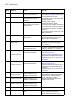
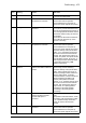
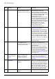


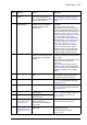
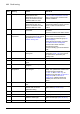
Table Of Contents
- Introduction to the manual
- Using the control panel
- Control locations and operating modes
- Program features
- What this chapter contains
- Drive configuration and programming
- Control interfaces
- Motor control
- Direct torque control (DTC)
- Reference ramping
- Constant speeds/frequencies
- Critical speeds/frequencies
- Speed controller autotune
- Oscillation damping
- Rush control
- Encoder support
- Encoder echo and emulation
- Load and motor feedback
- Position counter
- Encoder error handling
- Reading/writing position counter values through fieldbus
- Configuration of HTL encoder motor feedback
- Example 1: Using the same encoder for both load and motor feedback
- Example 2: Using two encoders
- Example 3: ACS 600 / ACS800 compatibility
- Settings
- Jogging
- Scalar motor control
- Autophasing
- Flux braking
- DC magnetization
- Application control
- DC voltage control
- Safety and protections
- Emergency stop
- Motor thermal protection
- Thermal protection of motor cable
- User load curve
- Other programmable protection functions
- External events (parameters 31.01…31.10)
- Motor phase loss detection (parameter 31.19)
- Earth (Ground) fault detection (parameter 31.20)
- Supply phase loss detection (parameter 31.21)
- Safe torque off detection (parameter 31.22)
- Swapped supply and motor cabling (parameter 31.23)
- Stall protection (parameters 31.24…31.28)
- Overspeed protection (parameter 31.30)
- Ramp stop supervision (parameters 31.32, 31.33, 31.37 and 31.38)
- Custom motor current fault limit (parameter 31.42)
- Local control loss detection (parameter 49.05)
- Automatic fault resets
- Diagnostics
- Miscellaneous
- Application macros
- Parameters
- 01 Actual values
- 03 Input references
- 04 Warnings and faults
- 05 Diagnostics
- 06 Control and status words
- 07 System info
- 10 Standard DI, RO
- 11 Standard DIO, FI, FO
- 12 Standard AI
- 13 Standard AO
- 14 I/O extension module 1
- 15 I/O extension module 2
- 16 I/O extension module 3
- 19 Operation mode
- 20 Start/stop/direction
- 21 Start/stop mode
- 22 Speed reference selection
- 23 Speed reference ramp
- 24 Speed reference conditioning
- 25 Speed control
- 26 Torque reference chain
- 28 Frequency reference chain
- 30 Limits
- 31 Fault functions
- 32 Supervision
- 33 Generic timer & counter
- 35 Motor thermal protection
- 36 Load analyzer
- 37 User load curve
- 40 Process PID set 1
- 41 Process PID set 2
- 43 Brake chopper
- 44 Mechanical brake control
- 45 Energy efficiency
- 46 Monitoring/scaling settings
- 47 Data storage
- 49 Panel port communication
- 50 Fieldbus adapter (FBA)
- 51 FBA A settings
- 52 FBA A data in
- 53 FBA A data out
- 54 FBA B settings
- 55 FBA B data in
- 56 FBA B data out
- 58 Embedded fieldbus
- 60 DDCS communication
- 61 D2D and DDCS transmit data
- 62 D2D and DDCS receive data
- 90 Feedback selection
- 91 Encoder module settings
- 92 Encoder 1 configuration
- 93 Encoder 2 configuration
- 94 LSU control
- 95 HW configuration
- 96 System
- 97 Motor control
- 98 User motor parameters
- 99 Motor data
- 200 Safety
- Additional parameter data
- Fault tracing
- Fieldbus control through the embedded fieldbus interface (EFB)
- What this chapter contains
- System overview
- Connecting the fieldbus to the drive
- Setting up the embedded fieldbus interface
- Setting the drive control parameters
- Basics of the embedded fieldbus interface
- About the control profiles
- The ABB Drives profile
- The Transparent profile
- Modbus function codes
- Exception codes
- Coils (0xxxx reference set)
- Discrete inputs (1xxxx reference set)
- Error code registers (holding registers 400090…400100)
- Fieldbus control through a fieldbus adapter
- What this chapter contains
- System overview
- Basics of the fieldbus control interface
- Setting up the drive for fieldbus control
- Control chain diagrams
- What this chapter contains
- Speed reference source selection I
- Speed reference source selection II
- Speed reference ramping and shaping
- Motor feedback configuration
- Load feedback and position counter configuration
- Speed error calculation
- Speed controller
- Torque reference source selection and modification
- Operating mode selection
- Reference selection for torque controller
- Torque limitation
- Torque controller
- Frequency reference selection
- Frequency reference modification
- Process PID setpoint and feedback source selection
- Process PID controller
- Master/Follower communication I (Master)
- Master/Follower communication II (Follower)
- Further information

478 Fault tracing
A687 Checksum
configuration
An action has been defined for
a parameter checksum
mismatch but the feature has
not been configured.
Contact your local ABB representative for
configuring the feature, or disable the
feature in 96.54 Checksum action.
A688 Parameter map
configuration
Too much data in parameter
mapping table created in Drive
customizer.
See the Drive customizer PC tool user’s
manual (3AUA0000104167 [English]).
A689 Mapped parameter
value cut
Parameter value saturated eg.
by the scaling specified in
parameter mapping table
(created in Drive customizer).
Check parameter scaling and format in
parameter mapping table. See the Drive
customizer PC tool user’s manual
(3AUA0000104167 [English]).
A6A4 Motor nominal value The motor parameters are set
incorrectly.
Check the auxiliary code. See actions for
each code below.
The drive is not dimensioned
correctly.
1 Slip frequency is too small Check the settings of the motor
configuration parameters in groups 98
and 99.
Check that the drive is sized correctly for
the motor.
2 Synchronous and nominal
speeds differ too much
3 Nominal speed is higher than
synchronous speed with 1 pole
pair
4 Nominal current is outside
limits
5 Nominal voltage is outside
limits
6 Nominal power is higher than
apparent power
7 Nominal power not consistent
with nominal speed and torque
A6A5 No motor data Parameters in group 99 have
not been set.
Check that all the required parameters in
group 99 have been set.
Note: It is normal for this warning to
appear during the start-up and continue
until the motor data is entered.
A6A6 Supply voltage
unselected
The supply voltage has not
been defined.
Set supply voltage in parameter 95.01
Supply voltage.
A6B0 User lock is open The user lock is open, ie. user
lock configuration parameters
96.100…96.102 are visible.
Close the user lock by entering an invalid
pass code in parameter 96.02 Pass
code. See section User lock (page 91).
A6B1 User pass code not
confirmed
A new user pass code has
been entered in parameter
96.100 but not confirmed in
96.101.
Confirm the new pass code by entering
the same code in 96.101. To cancel,
close the user lock without confirming the
new code. See section User lock (page
91).
A6D1 FBA A parameter
conflict
The drive does not have a
functionality requested by a
PLC, or requested functionality
has not been activated.
Check PLC programming.
Check settings of parameter groups 50
Fieldbus adapter (FBA) and 51 FBA A
settings.
Code
(hex)
Warning Cause What to do