
Firmware Manual

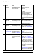
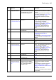

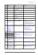


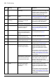


Table Of Contents
- Introduction to the manual
- Using the control panel
- Control locations and operating modes
- Program features
- What this chapter contains
- Drive configuration and programming
- Control interfaces
- Motor control
- Direct torque control (DTC)
- Reference ramping
- Constant speeds/frequencies
- Critical speeds/frequencies
- Speed controller autotune
- Oscillation damping
- Rush control
- Encoder support
- Encoder echo and emulation
- Load and motor feedback
- Position counter
- Encoder error handling
- Reading/writing position counter values through fieldbus
- Configuration of HTL encoder motor feedback
- Example 1: Using the same encoder for both load and motor feedback
- Example 2: Using two encoders
- Example 3: ACS 600 / ACS800 compatibility
- Settings
- Jogging
- Scalar motor control
- Autophasing
- Flux braking
- DC magnetization
- Application control
- DC voltage control
- Safety and protections
- Emergency stop
- Motor thermal protection
- Thermal protection of motor cable
- User load curve
- Other programmable protection functions
- External events (parameters 31.01…31.10)
- Motor phase loss detection (parameter 31.19)
- Earth (Ground) fault detection (parameter 31.20)
- Supply phase loss detection (parameter 31.21)
- Safe torque off detection (parameter 31.22)
- Swapped supply and motor cabling (parameter 31.23)
- Stall protection (parameters 31.24…31.28)
- Overspeed protection (parameter 31.30)
- Ramp stop supervision (parameters 31.32, 31.33, 31.37 and 31.38)
- Custom motor current fault limit (parameter 31.42)
- Local control loss detection (parameter 49.05)
- Automatic fault resets
- Diagnostics
- Miscellaneous
- Application macros
- Parameters
- 01 Actual values
- 03 Input references
- 04 Warnings and faults
- 05 Diagnostics
- 06 Control and status words
- 07 System info
- 10 Standard DI, RO
- 11 Standard DIO, FI, FO
- 12 Standard AI
- 13 Standard AO
- 14 I/O extension module 1
- 15 I/O extension module 2
- 16 I/O extension module 3
- 19 Operation mode
- 20 Start/stop/direction
- 21 Start/stop mode
- 22 Speed reference selection
- 23 Speed reference ramp
- 24 Speed reference conditioning
- 25 Speed control
- 26 Torque reference chain
- 28 Frequency reference chain
- 30 Limits
- 31 Fault functions
- 32 Supervision
- 33 Generic timer & counter
- 35 Motor thermal protection
- 36 Load analyzer
- 37 User load curve
- 40 Process PID set 1
- 41 Process PID set 2
- 43 Brake chopper
- 44 Mechanical brake control
- 45 Energy efficiency
- 46 Monitoring/scaling settings
- 47 Data storage
- 49 Panel port communication
- 50 Fieldbus adapter (FBA)
- 51 FBA A settings
- 52 FBA A data in
- 53 FBA A data out
- 54 FBA B settings
- 55 FBA B data in
- 56 FBA B data out
- 58 Embedded fieldbus
- 60 DDCS communication
- 61 D2D and DDCS transmit data
- 62 D2D and DDCS receive data
- 90 Feedback selection
- 91 Encoder module settings
- 92 Encoder 1 configuration
- 93 Encoder 2 configuration
- 94 LSU control
- 95 HW configuration
- 96 System
- 97 Motor control
- 98 User motor parameters
- 99 Motor data
- 200 Safety
- Additional parameter data
- Fault tracing
- Fieldbus control through the embedded fieldbus interface (EFB)
- What this chapter contains
- System overview
- Connecting the fieldbus to the drive
- Setting up the embedded fieldbus interface
- Setting the drive control parameters
- Basics of the embedded fieldbus interface
- About the control profiles
- The ABB Drives profile
- The Transparent profile
- Modbus function codes
- Exception codes
- Coils (0xxxx reference set)
- Discrete inputs (1xxxx reference set)
- Error code registers (holding registers 400090…400100)
- Fieldbus control through a fieldbus adapter
- What this chapter contains
- System overview
- Basics of the fieldbus control interface
- Setting up the drive for fieldbus control
- Control chain diagrams
- What this chapter contains
- Speed reference source selection I
- Speed reference source selection II
- Speed reference ramping and shaping
- Motor feedback configuration
- Load feedback and position counter configuration
- Speed error calculation
- Speed controller
- Torque reference source selection and modification
- Operating mode selection
- Reference selection for torque controller
- Torque limitation
- Torque controller
- Frequency reference selection
- Frequency reference modification
- Process PID setpoint and feedback source selection
- Process PID controller
- Master/Follower communication I (Master)
- Master/Follower communication II (Follower)
- Further information

482 Fault tracing
A79C BC IGBT excess
temperature
Brake chopper IGBT
temperature has exceeded
internal warning limit.
Let chopper cool down.
Check for excessive ambient
temperature.
Check for cooling fan failure.
Check for obstructions in the air flow.
Check the dimensioning and cooling of
the cabinet.
Check resistor overload protection
function settings (parameters
43.06…43.10).
Check minimum allowed resistor value
for the chopper being used.
Check that braking cycle meets allowed
limits.
Check that drive supply AC voltage is not
excessive.
A7A1 Mechanical brake
closing failed
Programmable warning:
44.17 Brake fault function
Status of mechanical brake
acknowledgement is not as
expected during brake close.
Check mechanical brake connection.
Check mechanical brake settings in
parameter group 44 Mechanical brake
control.
Check that acknowledgement signal
matches actual status of brake.
A7A2 Mechanical brake
opening failed
Programmable warning:
44.17 Brake fault function
Status of mechanical brake
acknowledgement is not as
expected during brake open.
Check mechanical brake connection.
Check mechanical brake settings in
parameter group 44 Mechanical brake
control.
Check that acknowledgement signal
matches actual status of brake.
A7A5 Mechanical brake
opening not allowed
Programmable warning:
44.17 Brake fault function
Open conditions of mechanical
brake cannot be fulfilled (for
example, brake has been
prevented from opening by
parameter 44.11 Keep brake
closed).
Check mechanical brake settings in
parameter group 44 Mechanical brake
control (especially 44.11 Keep brake
closed).
Check that acknowledgement signal (if
used) matches actual status of brake.
A7AA Extension AI
parameterization
The hardware current/voltage
setting of an analog input (on
an I/O extension module) does
not correspond to parameter
settings.
Check the auxiliary code (format
XX00 00YY). “XX” specifies the number
of the I/O extension module (01:
parameter group 14 I/O extension
module 1, 02: 15 I/O extension module 2,
03: 16 I/O extension module 3). “YY”
specifies the analog input on the module.
For example, in case of I/O extension
module 1, analog input AI1 (auxiliary
code 0000 0101), the hardware
current/voltage setting on the module is
shown by parameter 14.29. The
corresponding parameter setting is
14.30. Adjust either the hardware setting
on the module or the parameter to solve
the mismatch.
Note: Control board reboot (either by
cycling the power or through parameter
96.08 Control board boot) is required to
validate any changes in the hardware
settings.
Code
(hex)
Warning Cause What to do