
Firmware Manual

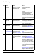
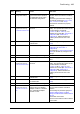

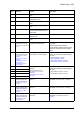


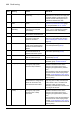


Table Of Contents
- Introduction to the manual
- Using the control panel
- Control locations and operating modes
- Program features
- What this chapter contains
- Drive configuration and programming
- Control interfaces
- Motor control
- Direct torque control (DTC)
- Reference ramping
- Constant speeds/frequencies
- Critical speeds/frequencies
- Speed controller autotune
- Oscillation damping
- Rush control
- Encoder support
- Encoder echo and emulation
- Load and motor feedback
- Position counter
- Encoder error handling
- Reading/writing position counter values through fieldbus
- Configuration of HTL encoder motor feedback
- Example 1: Using the same encoder for both load and motor feedback
- Example 2: Using two encoders
- Example 3: ACS 600 / ACS800 compatibility
- Settings
- Jogging
- Scalar motor control
- Autophasing
- Flux braking
- DC magnetization
- Application control
- DC voltage control
- Safety and protections
- Emergency stop
- Motor thermal protection
- Thermal protection of motor cable
- User load curve
- Other programmable protection functions
- External events (parameters 31.01…31.10)
- Motor phase loss detection (parameter 31.19)
- Earth (Ground) fault detection (parameter 31.20)
- Supply phase loss detection (parameter 31.21)
- Safe torque off detection (parameter 31.22)
- Swapped supply and motor cabling (parameter 31.23)
- Stall protection (parameters 31.24…31.28)
- Overspeed protection (parameter 31.30)
- Ramp stop supervision (parameters 31.32, 31.33, 31.37 and 31.38)
- Custom motor current fault limit (parameter 31.42)
- Local control loss detection (parameter 49.05)
- Automatic fault resets
- Diagnostics
- Miscellaneous
- Application macros
- Parameters
- 01 Actual values
- 03 Input references
- 04 Warnings and faults
- 05 Diagnostics
- 06 Control and status words
- 07 System info
- 10 Standard DI, RO
- 11 Standard DIO, FI, FO
- 12 Standard AI
- 13 Standard AO
- 14 I/O extension module 1
- 15 I/O extension module 2
- 16 I/O extension module 3
- 19 Operation mode
- 20 Start/stop/direction
- 21 Start/stop mode
- 22 Speed reference selection
- 23 Speed reference ramp
- 24 Speed reference conditioning
- 25 Speed control
- 26 Torque reference chain
- 28 Frequency reference chain
- 30 Limits
- 31 Fault functions
- 32 Supervision
- 33 Generic timer & counter
- 35 Motor thermal protection
- 36 Load analyzer
- 37 User load curve
- 40 Process PID set 1
- 41 Process PID set 2
- 43 Brake chopper
- 44 Mechanical brake control
- 45 Energy efficiency
- 46 Monitoring/scaling settings
- 47 Data storage
- 49 Panel port communication
- 50 Fieldbus adapter (FBA)
- 51 FBA A settings
- 52 FBA A data in
- 53 FBA A data out
- 54 FBA B settings
- 55 FBA B data in
- 56 FBA B data out
- 58 Embedded fieldbus
- 60 DDCS communication
- 61 D2D and DDCS transmit data
- 62 D2D and DDCS receive data
- 90 Feedback selection
- 91 Encoder module settings
- 92 Encoder 1 configuration
- 93 Encoder 2 configuration
- 94 LSU control
- 95 HW configuration
- 96 System
- 97 Motor control
- 98 User motor parameters
- 99 Motor data
- 200 Safety
- Additional parameter data
- Fault tracing
- Fieldbus control through the embedded fieldbus interface (EFB)
- What this chapter contains
- System overview
- Connecting the fieldbus to the drive
- Setting up the embedded fieldbus interface
- Setting the drive control parameters
- Basics of the embedded fieldbus interface
- About the control profiles
- The ABB Drives profile
- The Transparent profile
- Modbus function codes
- Exception codes
- Coils (0xxxx reference set)
- Discrete inputs (1xxxx reference set)
- Error code registers (holding registers 400090…400100)
- Fieldbus control through a fieldbus adapter
- What this chapter contains
- System overview
- Basics of the fieldbus control interface
- Setting up the drive for fieldbus control
- Control chain diagrams
- What this chapter contains
- Speed reference source selection I
- Speed reference source selection II
- Speed reference ramping and shaping
- Motor feedback configuration
- Load feedback and position counter configuration
- Speed error calculation
- Speed controller
- Torque reference source selection and modification
- Operating mode selection
- Reference selection for torque controller
- Torque limitation
- Torque controller
- Frequency reference selection
- Frequency reference modification
- Process PID setpoint and feedback source selection
- Process PID controller
- Master/Follower communication I (Master)
- Master/Follower communication II (Follower)
- Further information

484 Fault tracing
A7C2 FBA B communication
Programmable warning:
50.32 FBA B comm loss
func
Cyclical communication
between drive and fieldbus
adapter module B or between
PLC and fieldbus adapter
module B is lost.
Check status of fieldbus communication.
See user documentation of fieldbus
interface.
Check settings of parameter group 50
Fieldbus adapter (FBA).
Check cable connections.
Check if communication master is able to
communicate.
A7CA DDCS controller
comm loss
Programmable warning:
60.59 DDCS controller
comm loss function
DDCS (fiber optic)
communication between drive
and external controller is lost.
Check status of controller. See user
documentation of controller.
Check settings of parameter group 60
DDCS communication.
Check cable connections. If necessary,
replace cables.
A7CB MF comm loss
Programmable warning:
60.09 M/F comm loss
function
Master/follower
communication is lost.
Check the auxiliary code. The code
indicates which node address (defined by
parameter 60.02 in each drive) on the
master/follower link is affected.
Check settings of parameter group 60
DDCS communication.
Check cable connections. If necessary,
replace cables.
A7CE EFB comm loss
Programmable warning:
58.14 Communication loss
action
Communication break in
embedded fieldbus (EFB)
communication.
Check the status of the fieldbus master
(online/offline/error etc.).
Check cable connections to the XD2D
connector on the control unit.
A7E1 Encoder
Programmable warning:
90.45 Motor feedback fault
Encoder error. Check the auxiliary code (format XXYY
ZZZZ). “XX” specifies the number of the
encoder interface module (01:
91.11/91.12, 02: 91.13/91.14), “YY”
specifies the encoder (01: 92 Encoder 1
configuration, 02: 93 Encoder 2
configuration). “ZZZZ” indicates the
problem (see actions for each code
below).
0001 Cable fault Check the conductor order at both ends
of the encoder cable.
Check the groundings of the encoder
cable.
If the encoder was working previously,
check the encoder, encoder cable and
encoder interface module for damage.
See also parameter 92.21 Encoder cable
fault mode.
0002 No encoder signal Check the condition of the encoder.
0003 Overspeed Contact your local ABB representative.
0004 Overfrequency Contact your local ABB representative.
0005 Resolver ID run failed Contact your local ABB representative.
0006 Resolver overcurrent fault Contact your local ABB representative.
0007 Speed scaling error Contact your local ABB representative.
0008 Absolute encoder
communication error
Contact your local ABB representative.
Code
(hex)
Warning Cause What to do