
Firmware Manual
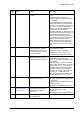
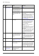
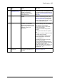
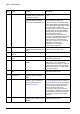
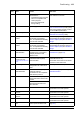
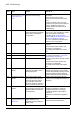
Table Of Contents
- Introduction to the manual
- Using the control panel
- Control locations and operating modes
- Program features
- What this chapter contains
- Drive configuration and programming
- Control interfaces
- Motor control
- Direct torque control (DTC)
- Reference ramping
- Constant speeds/frequencies
- Critical speeds/frequencies
- Speed controller autotune
- Oscillation damping
- Rush control
- Encoder support
- Encoder echo and emulation
- Load and motor feedback
- Position counter
- Encoder error handling
- Reading/writing position counter values through fieldbus
- Configuration of HTL encoder motor feedback
- Example 1: Using the same encoder for both load and motor feedback
- Example 2: Using two encoders
- Example 3: ACS 600 / ACS800 compatibility
- Settings
- Jogging
- Scalar motor control
- Autophasing
- Flux braking
- DC magnetization
- Application control
- DC voltage control
- Safety and protections
- Emergency stop
- Motor thermal protection
- Thermal protection of motor cable
- User load curve
- Other programmable protection functions
- External events (parameters 31.01…31.10)
- Motor phase loss detection (parameter 31.19)
- Earth (Ground) fault detection (parameter 31.20)
- Supply phase loss detection (parameter 31.21)
- Safe torque off detection (parameter 31.22)
- Swapped supply and motor cabling (parameter 31.23)
- Stall protection (parameters 31.24…31.28)
- Overspeed protection (parameter 31.30)
- Ramp stop supervision (parameters 31.32, 31.33, 31.37 and 31.38)
- Custom motor current fault limit (parameter 31.42)
- Local control loss detection (parameter 49.05)
- Automatic fault resets
- Diagnostics
- Miscellaneous
- Application macros
- Parameters
- 01 Actual values
- 03 Input references
- 04 Warnings and faults
- 05 Diagnostics
- 06 Control and status words
- 07 System info
- 10 Standard DI, RO
- 11 Standard DIO, FI, FO
- 12 Standard AI
- 13 Standard AO
- 14 I/O extension module 1
- 15 I/O extension module 2
- 16 I/O extension module 3
- 19 Operation mode
- 20 Start/stop/direction
- 21 Start/stop mode
- 22 Speed reference selection
- 23 Speed reference ramp
- 24 Speed reference conditioning
- 25 Speed control
- 26 Torque reference chain
- 28 Frequency reference chain
- 30 Limits
- 31 Fault functions
- 32 Supervision
- 33 Generic timer & counter
- 35 Motor thermal protection
- 36 Load analyzer
- 37 User load curve
- 40 Process PID set 1
- 41 Process PID set 2
- 43 Brake chopper
- 44 Mechanical brake control
- 45 Energy efficiency
- 46 Monitoring/scaling settings
- 47 Data storage
- 49 Panel port communication
- 50 Fieldbus adapter (FBA)
- 51 FBA A settings
- 52 FBA A data in
- 53 FBA A data out
- 54 FBA B settings
- 55 FBA B data in
- 56 FBA B data out
- 58 Embedded fieldbus
- 60 DDCS communication
- 61 D2D and DDCS transmit data
- 62 D2D and DDCS receive data
- 90 Feedback selection
- 91 Encoder module settings
- 92 Encoder 1 configuration
- 93 Encoder 2 configuration
- 94 LSU control
- 95 HW configuration
- 96 System
- 97 Motor control
- 98 User motor parameters
- 99 Motor data
- 200 Safety
- Additional parameter data
- Fault tracing
- Fieldbus control through the embedded fieldbus interface (EFB)
- What this chapter contains
- System overview
- Connecting the fieldbus to the drive
- Setting up the embedded fieldbus interface
- Setting the drive control parameters
- Basics of the embedded fieldbus interface
- About the control profiles
- The ABB Drives profile
- The Transparent profile
- Modbus function codes
- Exception codes
- Coils (0xxxx reference set)
- Discrete inputs (1xxxx reference set)
- Error code registers (holding registers 400090…400100)
- Fieldbus control through a fieldbus adapter
- What this chapter contains
- System overview
- Basics of the fieldbus control interface
- Setting up the drive for fieldbus control
- Control chain diagrams
- What this chapter contains
- Speed reference source selection I
- Speed reference source selection II
- Speed reference ramping and shaping
- Motor feedback configuration
- Load feedback and position counter configuration
- Speed error calculation
- Speed controller
- Torque reference source selection and modification
- Operating mode selection
- Reference selection for torque controller
- Torque limitation
- Torque controller
- Frequency reference selection
- Frequency reference modification
- Process PID setpoint and feedback source selection
- Process PID controller
- Master/Follower communication I (Master)
- Master/Follower communication II (Follower)
- Further information

Fault tracing 495
5091 Safe torque off
Programmable fault: 31.22
STO indication run/stop
Safe torque off function is
active, i.e. safety circuit
signal(s) connected to
connector XSTO is broken
during start or run.
Check safe torque off circuit connections.
For more information, see appropriate
drive hardware manual and description of
parameter 31.22 STO indication run/stop
(page 258).
5092 PU logic error Power unit memory has
cleared.
Cycle the power to the drive. If the
control unit is externally powered, also
reboot the control unit (using parameter
96.08 Control board boot) or by cycling
its power. If the problem persists, contact
your local ABB representative.
5093 Rating ID mismatch The hardware of the drive does
not match the information
stored in the memory unit. This
may occur eg. after a firmware
update or memory unit
replacement.
Cycle the power to the drive.
Check the auxiliary code. The auxiliary
code categories are as follows:
1 = PU and CU ratings not the same.
Rating ID has changed.
2 = Parallel connection rating ID has
changed.
3 = PU types not the same in all power
units.
4 = Parallel connection rating ID is active
in a single power unit setup.
5 = It is not possible to implement the
selected rating with the current PUs.
6 = PU rating ID is 0.
7 = Reading PU rating ID or PU type
failed on PU connection.
8 = PU not supported (illegal rating ID).
With parallel connection faults, the format
of the auxiliary code is 0X0Y. “Y”
indicates the auxiliary code category, “X”
indicates the first faulty PU channel in
hexadecimal (1…C).
5094 Measurement circuit
temperature
Problem with internal
temperature measurement of
the drive.
See A5EA Measurement circuit
temperature (page 476).
Code
(hex)
Fault Cause What to do