
Firmware Manual
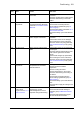

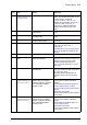

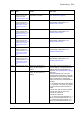
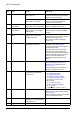
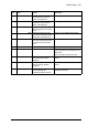


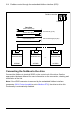
Table Of Contents
- Introduction to the manual
- Using the control panel
- Control locations and operating modes
- Program features
- What this chapter contains
- Drive configuration and programming
- Control interfaces
- Motor control
- Direct torque control (DTC)
- Reference ramping
- Constant speeds/frequencies
- Critical speeds/frequencies
- Speed controller autotune
- Oscillation damping
- Rush control
- Encoder support
- Encoder echo and emulation
- Load and motor feedback
- Position counter
- Encoder error handling
- Reading/writing position counter values through fieldbus
- Configuration of HTL encoder motor feedback
- Example 1: Using the same encoder for both load and motor feedback
- Example 2: Using two encoders
- Example 3: ACS 600 / ACS800 compatibility
- Settings
- Jogging
- Scalar motor control
- Autophasing
- Flux braking
- DC magnetization
- Application control
- DC voltage control
- Safety and protections
- Emergency stop
- Motor thermal protection
- Thermal protection of motor cable
- User load curve
- Other programmable protection functions
- External events (parameters 31.01…31.10)
- Motor phase loss detection (parameter 31.19)
- Earth (Ground) fault detection (parameter 31.20)
- Supply phase loss detection (parameter 31.21)
- Safe torque off detection (parameter 31.22)
- Swapped supply and motor cabling (parameter 31.23)
- Stall protection (parameters 31.24…31.28)
- Overspeed protection (parameter 31.30)
- Ramp stop supervision (parameters 31.32, 31.33, 31.37 and 31.38)
- Custom motor current fault limit (parameter 31.42)
- Local control loss detection (parameter 49.05)
- Automatic fault resets
- Diagnostics
- Miscellaneous
- Application macros
- Parameters
- 01 Actual values
- 03 Input references
- 04 Warnings and faults
- 05 Diagnostics
- 06 Control and status words
- 07 System info
- 10 Standard DI, RO
- 11 Standard DIO, FI, FO
- 12 Standard AI
- 13 Standard AO
- 14 I/O extension module 1
- 15 I/O extension module 2
- 16 I/O extension module 3
- 19 Operation mode
- 20 Start/stop/direction
- 21 Start/stop mode
- 22 Speed reference selection
- 23 Speed reference ramp
- 24 Speed reference conditioning
- 25 Speed control
- 26 Torque reference chain
- 28 Frequency reference chain
- 30 Limits
- 31 Fault functions
- 32 Supervision
- 33 Generic timer & counter
- 35 Motor thermal protection
- 36 Load analyzer
- 37 User load curve
- 40 Process PID set 1
- 41 Process PID set 2
- 43 Brake chopper
- 44 Mechanical brake control
- 45 Energy efficiency
- 46 Monitoring/scaling settings
- 47 Data storage
- 49 Panel port communication
- 50 Fieldbus adapter (FBA)
- 51 FBA A settings
- 52 FBA A data in
- 53 FBA A data out
- 54 FBA B settings
- 55 FBA B data in
- 56 FBA B data out
- 58 Embedded fieldbus
- 60 DDCS communication
- 61 D2D and DDCS transmit data
- 62 D2D and DDCS receive data
- 90 Feedback selection
- 91 Encoder module settings
- 92 Encoder 1 configuration
- 93 Encoder 2 configuration
- 94 LSU control
- 95 HW configuration
- 96 System
- 97 Motor control
- 98 User motor parameters
- 99 Motor data
- 200 Safety
- Additional parameter data
- Fault tracing
- Fieldbus control through the embedded fieldbus interface (EFB)
- What this chapter contains
- System overview
- Connecting the fieldbus to the drive
- Setting up the embedded fieldbus interface
- Setting the drive control parameters
- Basics of the embedded fieldbus interface
- About the control profiles
- The ABB Drives profile
- The Transparent profile
- Modbus function codes
- Exception codes
- Coils (0xxxx reference set)
- Discrete inputs (1xxxx reference set)
- Error code registers (holding registers 400090…400100)
- Fieldbus control through a fieldbus adapter
- What this chapter contains
- System overview
- Basics of the fieldbus control interface
- Setting up the drive for fieldbus control
- Control chain diagrams
- What this chapter contains
- Speed reference source selection I
- Speed reference source selection II
- Speed reference ramping and shaping
- Motor feedback configuration
- Load feedback and position counter configuration
- Speed error calculation
- Speed controller
- Torque reference source selection and modification
- Operating mode selection
- Reference selection for torque controller
- Torque limitation
- Torque controller
- Frequency reference selection
- Frequency reference modification
- Process PID setpoint and feedback source selection
- Process PID controller
- Master/Follower communication I (Master)
- Master/Follower communication II (Follower)
- Further information

Fault tracing 505
80B2 Signal supervision 3
(Editable message text)
Programmable fault:
32.26 Supervision 3 action
Fault generated by the signal
supervision 3 function.
Check the source of the fault (parameter
32.27 Supervision 3 signal).
9081 External fault 1
(Editable message text)
Programmable fault: 31.01
External event 1 source
31.02 External event 1
type
Fault in external device 1. Check the external device.
Check setting of parameter 31.01
External event 1 source.
9082 External fault 2
(Editable message text)
Programmable fault: 31.03
External event 2 source
31.04 External event 2
type
Fault in external device 2. Check the external device.
Check setting of parameter 31.03
External event 2 source.
9083 External fault 3
(Editable message text)
Programmable fault: 31.05
External event 3 source
31.06 External event 3
type
Fault in external device 3. Check the external device.
Check setting of parameter 31.05
External event 3 source.
9084 External fault 4
(Editable message text)
Programmable fault: 31.07
External event 4 source
31.08 External event 4
type
Fault in external device 4. Check the external device.
Check setting of parameter 31.07
External event 4 source.
9085 External fault 5
(Editable message text)
Programmable fault: 31.09
External event 5 source
31.10 External event 5
type
Fault in external device 5. Check the external device.
Check setting of parameter 31.09
External event 5 source.
FA81 Safe torque off 1 loss Safe torque off function is
active, ie. STO circuit 1 is
broken.
Check safety circuit connections. For
more information, see appropriate drive
hardware manual and description of
parameter 31.22 STO indication run/stop
(page 258).
Check the auxiliary code, The code
contains location information, especially
with parallel-connected inverter modules.
When converted into a 32-bit binary
number, the bits of the code indicate the
following:
31…28: Number of faulty inverter module
(0…11 decimal). 1111: STO_ACT states
of control unit and inverter modules in
conflict
27: STO_ACT state of inverter modules
26: STO_ACT state of control unit
25: STO1 of control unit
24: STO2 of control unit
23…12: STO1 of inverter modules 12…1
(Bits of non-existing modules set to 1)
11…0: STO2 of inverter modules 12…1
(Bits of non-existing modules set to 1)
FA82 Safe torque off 2 loss Safe torque off function is
active, ie. STO circuit 2 is
broken.
Code
(hex)
Fault Cause What to do