
Firmware Manual
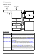


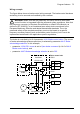
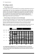

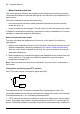
Table Of Contents
- Introduction to the manual
- Using the control panel
- Control locations and operating modes
- Program features
- What this chapter contains
- Drive configuration and programming
- Control interfaces
- Motor control
- Direct torque control (DTC)
- Reference ramping
- Constant speeds/frequencies
- Critical speeds/frequencies
- Speed controller autotune
- Oscillation damping
- Rush control
- Encoder support
- Encoder echo and emulation
- Load and motor feedback
- Position counter
- Encoder error handling
- Reading/writing position counter values through fieldbus
- Configuration of HTL encoder motor feedback
- Example 1: Using the same encoder for both load and motor feedback
- Example 2: Using two encoders
- Example 3: ACS 600 / ACS800 compatibility
- Settings
- Jogging
- Scalar motor control
- Autophasing
- Flux braking
- DC magnetization
- Application control
- DC voltage control
- Safety and protections
- Emergency stop
- Motor thermal protection
- Thermal protection of motor cable
- User load curve
- Other programmable protection functions
- External events (parameters 31.01…31.10)
- Motor phase loss detection (parameter 31.19)
- Earth (Ground) fault detection (parameter 31.20)
- Supply phase loss detection (parameter 31.21)
- Safe torque off detection (parameter 31.22)
- Swapped supply and motor cabling (parameter 31.23)
- Stall protection (parameters 31.24…31.28)
- Overspeed protection (parameter 31.30)
- Ramp stop supervision (parameters 31.32, 31.33, 31.37 and 31.38)
- Custom motor current fault limit (parameter 31.42)
- Local control loss detection (parameter 49.05)
- Automatic fault resets
- Diagnostics
- Miscellaneous
- Application macros
- Parameters
- 01 Actual values
- 03 Input references
- 04 Warnings and faults
- 05 Diagnostics
- 06 Control and status words
- 07 System info
- 10 Standard DI, RO
- 11 Standard DIO, FI, FO
- 12 Standard AI
- 13 Standard AO
- 14 I/O extension module 1
- 15 I/O extension module 2
- 16 I/O extension module 3
- 19 Operation mode
- 20 Start/stop/direction
- 21 Start/stop mode
- 22 Speed reference selection
- 23 Speed reference ramp
- 24 Speed reference conditioning
- 25 Speed control
- 26 Torque reference chain
- 28 Frequency reference chain
- 30 Limits
- 31 Fault functions
- 32 Supervision
- 33 Generic timer & counter
- 35 Motor thermal protection
- 36 Load analyzer
- 37 User load curve
- 40 Process PID set 1
- 41 Process PID set 2
- 43 Brake chopper
- 44 Mechanical brake control
- 45 Energy efficiency
- 46 Monitoring/scaling settings
- 47 Data storage
- 49 Panel port communication
- 50 Fieldbus adapter (FBA)
- 51 FBA A settings
- 52 FBA A data in
- 53 FBA A data out
- 54 FBA B settings
- 55 FBA B data in
- 56 FBA B data out
- 58 Embedded fieldbus
- 60 DDCS communication
- 61 D2D and DDCS transmit data
- 62 D2D and DDCS receive data
- 90 Feedback selection
- 91 Encoder module settings
- 92 Encoder 1 configuration
- 93 Encoder 2 configuration
- 94 LSU control
- 95 HW configuration
- 96 System
- 97 Motor control
- 98 User motor parameters
- 99 Motor data
- 200 Safety
- Additional parameter data
- Fault tracing
- Fieldbus control through the embedded fieldbus interface (EFB)
- What this chapter contains
- System overview
- Connecting the fieldbus to the drive
- Setting up the embedded fieldbus interface
- Setting the drive control parameters
- Basics of the embedded fieldbus interface
- About the control profiles
- The ABB Drives profile
- The Transparent profile
- Modbus function codes
- Exception codes
- Coils (0xxxx reference set)
- Discrete inputs (1xxxx reference set)
- Error code registers (holding registers 400090…400100)
- Fieldbus control through a fieldbus adapter
- What this chapter contains
- System overview
- Basics of the fieldbus control interface
- Setting up the drive for fieldbus control
- Control chain diagrams
- What this chapter contains
- Speed reference source selection I
- Speed reference source selection II
- Speed reference ramping and shaping
- Motor feedback configuration
- Load feedback and position counter configuration
- Speed error calculation
- Speed controller
- Torque reference source selection and modification
- Operating mode selection
- Reference selection for torque controller
- Torque limitation
- Torque controller
- Frequency reference selection
- Frequency reference modification
- Process PID setpoint and feedback source selection
- Process PID controller
- Master/Follower communication I (Master)
- Master/Follower communication II (Follower)
- Further information

78 Program features
Settings
Parameters 01.11 DC voltage (page 115), 30.30 Overvoltage control (page 254),
30.31 Undervoltage control (page 254), 95.01 Supply voltage (page 388), and 95.02
Adaptive voltage limits (page 388).
Brake chopper
A brake chopper can be used to handle the energy generated by a decelerating
motor. When the DC voltage rises high enough, the chopper connects the DC circuit
to an external brake resistor. The chopper operates on the pulse width modulation
principle.
The internal brake choppers of ACS880 drives start conducting when the DC link
voltage reaches 1.156 × U
DCmax
. 100% pulse width is reached at approximately 1.2 ×
U
DCmax
, depending on supply voltage range – see table under Voltage control and
trip limits above. (U
DCmax
is the DC voltage corresponding to the maximum of the AC
supply voltage range.) For information on external brake choppers, refer to their
documentation.
Note: For runtime braking, overvoltage control (parameter 30.30 Overvoltage control)
needs to be disabled for the chopper to operate.
Settings
Parameters 01.11 DC voltage (page 115) and 30.30 Overvoltage control (page 254);
parameter group 43 Brake chopper (page 307).
Supply voltage range [V] (see 95.01 Supply voltage)
Level 208…240 380…415 440…480 500 525…600 660…690
Overvoltage fault limit 489/440* 800 878 880 1113 1218
Overvoltage control limit 389 700 778 810 1013 1118
Internal brake chopper at 100%
pulse width
403 697 806 806 1008 1159
Internal brake chopper at 0%
pulse width
375 648 749 780 936 1077
Overvoltage warning limit 373 644 745 776 932 1071
DC voltage at upper bound of
supply voltage range (U
DCmax
)
324 560 648 675 810 932
DC voltage at lower bound of
supply voltage range
281 513 594 675 709 891
Undervoltage control and warning
limit
239 436 505 574 602 757
Charging activation/standby limit 225 410 475 540 567 713
Undervoltage fault limit 168 308 356 405 425 535
*489 V with frames R1…R3, 440 V with frames R4…R8.