
Firmware Manual


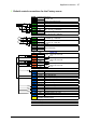
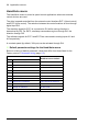
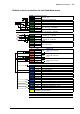
Table Of Contents
- Introduction to the manual
- Using the control panel
- Control locations and operating modes
- Program features
- What this chapter contains
- Drive configuration and programming
- Control interfaces
- Motor control
- Direct torque control (DTC)
- Reference ramping
- Constant speeds/frequencies
- Critical speeds/frequencies
- Speed controller autotune
- Oscillation damping
- Rush control
- Encoder support
- Encoder echo and emulation
- Load and motor feedback
- Position counter
- Encoder error handling
- Reading/writing position counter values through fieldbus
- Configuration of HTL encoder motor feedback
- Example 1: Using the same encoder for both load and motor feedback
- Example 2: Using two encoders
- Example 3: ACS 600 / ACS800 compatibility
- Settings
- Jogging
- Scalar motor control
- Autophasing
- Flux braking
- DC magnetization
- Application control
- DC voltage control
- Safety and protections
- Emergency stop
- Motor thermal protection
- Thermal protection of motor cable
- User load curve
- Other programmable protection functions
- External events (parameters 31.01…31.10)
- Motor phase loss detection (parameter 31.19)
- Earth (Ground) fault detection (parameter 31.20)
- Supply phase loss detection (parameter 31.21)
- Safe torque off detection (parameter 31.22)
- Swapped supply and motor cabling (parameter 31.23)
- Stall protection (parameters 31.24…31.28)
- Overspeed protection (parameter 31.30)
- Ramp stop supervision (parameters 31.32, 31.33, 31.37 and 31.38)
- Custom motor current fault limit (parameter 31.42)
- Local control loss detection (parameter 49.05)
- Automatic fault resets
- Diagnostics
- Miscellaneous
- Application macros
- Parameters
- 01 Actual values
- 03 Input references
- 04 Warnings and faults
- 05 Diagnostics
- 06 Control and status words
- 07 System info
- 10 Standard DI, RO
- 11 Standard DIO, FI, FO
- 12 Standard AI
- 13 Standard AO
- 14 I/O extension module 1
- 15 I/O extension module 2
- 16 I/O extension module 3
- 19 Operation mode
- 20 Start/stop/direction
- 21 Start/stop mode
- 22 Speed reference selection
- 23 Speed reference ramp
- 24 Speed reference conditioning
- 25 Speed control
- 26 Torque reference chain
- 28 Frequency reference chain
- 30 Limits
- 31 Fault functions
- 32 Supervision
- 33 Generic timer & counter
- 35 Motor thermal protection
- 36 Load analyzer
- 37 User load curve
- 40 Process PID set 1
- 41 Process PID set 2
- 43 Brake chopper
- 44 Mechanical brake control
- 45 Energy efficiency
- 46 Monitoring/scaling settings
- 47 Data storage
- 49 Panel port communication
- 50 Fieldbus adapter (FBA)
- 51 FBA A settings
- 52 FBA A data in
- 53 FBA A data out
- 54 FBA B settings
- 55 FBA B data in
- 56 FBA B data out
- 58 Embedded fieldbus
- 60 DDCS communication
- 61 D2D and DDCS transmit data
- 62 D2D and DDCS receive data
- 90 Feedback selection
- 91 Encoder module settings
- 92 Encoder 1 configuration
- 93 Encoder 2 configuration
- 94 LSU control
- 95 HW configuration
- 96 System
- 97 Motor control
- 98 User motor parameters
- 99 Motor data
- 200 Safety
- Additional parameter data
- Fault tracing
- Fieldbus control through the embedded fieldbus interface (EFB)
- What this chapter contains
- System overview
- Connecting the fieldbus to the drive
- Setting up the embedded fieldbus interface
- Setting the drive control parameters
- Basics of the embedded fieldbus interface
- About the control profiles
- The ABB Drives profile
- The Transparent profile
- Modbus function codes
- Exception codes
- Coils (0xxxx reference set)
- Discrete inputs (1xxxx reference set)
- Error code registers (holding registers 400090…400100)
- Fieldbus control through a fieldbus adapter
- What this chapter contains
- System overview
- Basics of the fieldbus control interface
- Setting up the drive for fieldbus control
- Control chain diagrams
- What this chapter contains
- Speed reference source selection I
- Speed reference source selection II
- Speed reference ramping and shaping
- Motor feedback configuration
- Load feedback and position counter configuration
- Speed error calculation
- Speed controller
- Torque reference source selection and modification
- Operating mode selection
- Reference selection for torque controller
- Torque limitation
- Torque controller
- Frequency reference selection
- Frequency reference modification
- Process PID setpoint and feedback source selection
- Process PID controller
- Master/Follower communication I (Master)
- Master/Follower communication II (Follower)
- Further information

92 Program features
Activation of the reduced run function
Note: For cabinet-built drives, the wiring accessories and the air baffle needed during
the procedure are available from ABB, and are included in the delivery.
WARNING! Follow the safety instructions provided for the drive or
inverter unit in question.
1. Disconnect the supply voltage and all auxiliary voltages from the drive/inverter
unit.
2. If the inverter control unit is powered from the faulty module, install an extension
to the wiring and connect it to one of the remaining modules.
3. Remove the module to be serviced from its bay. See the appropriate hardware
manual for instructions.
4. If the Safe torque off (STO) function is in use, install jumpering in the STO wiring
in place of the missing module (unless the module was the last on the chain).
5. Install an air baffle to the top module guide to block the airflow through the empty
module bay.
6. In case the inverter unit has a DC switch with a charging circuit, disable the
appropriate channel on the xSFC-xx charging controller.
7. Switch on the power to the drive/inverter unit.
8. Enter the number of inverter modules present into parameter 95.13 Reduced run
mode.
9. Reset all faults and start the drive/inverter unit. The maximum current is now
automatically limited according to the new inverter configuration. A mismatch
between the number of detected modules (95.14) and the value set in 95.13 will
generate a fault.
After all modules have been reinstalled, parameter 95.13 Reduced run mode must be
reset to 0 to disable the reduced run function. In case the inverter is equipped with a
charging circuit, the charging monitoring must be reactivated for all modules. If the
Safe torque off (STO) function is in use, an acceptance test must be performed (see
the hardware manual of the drive/inverter unit for instructions).
Settings
Parameters 06.17 (page 129) and 95.13…95.14 (page 390).
du/dt filter support
With an external du/dt filter connected to the output of the drive, bit 13 of 95.20 HW
options word 1 must be switched on. The setting enables an overtemperature