
Firmware Manual


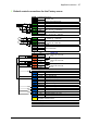
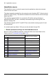
Table Of Contents
- Introduction to the manual
- Using the control panel
- Control locations and operating modes
- Program features
- What this chapter contains
- Drive configuration and programming
- Control interfaces
- Motor control
- Direct torque control (DTC)
- Reference ramping
- Constant speeds/frequencies
- Critical speeds/frequencies
- Speed controller autotune
- Oscillation damping
- Rush control
- Encoder support
- Encoder echo and emulation
- Load and motor feedback
- Position counter
- Encoder error handling
- Reading/writing position counter values through fieldbus
- Configuration of HTL encoder motor feedback
- Example 1: Using the same encoder for both load and motor feedback
- Example 2: Using two encoders
- Example 3: ACS 600 / ACS800 compatibility
- Settings
- Jogging
- Scalar motor control
- Autophasing
- Flux braking
- DC magnetization
- Application control
- DC voltage control
- Safety and protections
- Emergency stop
- Motor thermal protection
- Thermal protection of motor cable
- User load curve
- Other programmable protection functions
- External events (parameters 31.01…31.10)
- Motor phase loss detection (parameter 31.19)
- Earth (Ground) fault detection (parameter 31.20)
- Supply phase loss detection (parameter 31.21)
- Safe torque off detection (parameter 31.22)
- Swapped supply and motor cabling (parameter 31.23)
- Stall protection (parameters 31.24…31.28)
- Overspeed protection (parameter 31.30)
- Ramp stop supervision (parameters 31.32, 31.33, 31.37 and 31.38)
- Custom motor current fault limit (parameter 31.42)
- Local control loss detection (parameter 49.05)
- Automatic fault resets
- Diagnostics
- Miscellaneous
- Application macros
- Parameters
- 01 Actual values
- 03 Input references
- 04 Warnings and faults
- 05 Diagnostics
- 06 Control and status words
- 07 System info
- 10 Standard DI, RO
- 11 Standard DIO, FI, FO
- 12 Standard AI
- 13 Standard AO
- 14 I/O extension module 1
- 15 I/O extension module 2
- 16 I/O extension module 3
- 19 Operation mode
- 20 Start/stop/direction
- 21 Start/stop mode
- 22 Speed reference selection
- 23 Speed reference ramp
- 24 Speed reference conditioning
- 25 Speed control
- 26 Torque reference chain
- 28 Frequency reference chain
- 30 Limits
- 31 Fault functions
- 32 Supervision
- 33 Generic timer & counter
- 35 Motor thermal protection
- 36 Load analyzer
- 37 User load curve
- 40 Process PID set 1
- 41 Process PID set 2
- 43 Brake chopper
- 44 Mechanical brake control
- 45 Energy efficiency
- 46 Monitoring/scaling settings
- 47 Data storage
- 49 Panel port communication
- 50 Fieldbus adapter (FBA)
- 51 FBA A settings
- 52 FBA A data in
- 53 FBA A data out
- 54 FBA B settings
- 55 FBA B data in
- 56 FBA B data out
- 58 Embedded fieldbus
- 60 DDCS communication
- 61 D2D and DDCS transmit data
- 62 D2D and DDCS receive data
- 90 Feedback selection
- 91 Encoder module settings
- 92 Encoder 1 configuration
- 93 Encoder 2 configuration
- 94 LSU control
- 95 HW configuration
- 96 System
- 97 Motor control
- 98 User motor parameters
- 99 Motor data
- 200 Safety
- Additional parameter data
- Fault tracing
- Fieldbus control through the embedded fieldbus interface (EFB)
- What this chapter contains
- System overview
- Connecting the fieldbus to the drive
- Setting up the embedded fieldbus interface
- Setting the drive control parameters
- Basics of the embedded fieldbus interface
- About the control profiles
- The ABB Drives profile
- The Transparent profile
- Modbus function codes
- Exception codes
- Coils (0xxxx reference set)
- Discrete inputs (1xxxx reference set)
- Error code registers (holding registers 400090…400100)
- Fieldbus control through a fieldbus adapter
- What this chapter contains
- System overview
- Basics of the fieldbus control interface
- Setting up the drive for fieldbus control
- Control chain diagrams
- What this chapter contains
- Speed reference source selection I
- Speed reference source selection II
- Speed reference ramping and shaping
- Motor feedback configuration
- Load feedback and position counter configuration
- Speed error calculation
- Speed controller
- Torque reference source selection and modification
- Operating mode selection
- Reference selection for torque controller
- Torque limitation
- Torque controller
- Frequency reference selection
- Frequency reference modification
- Process PID setpoint and feedback source selection
- Process PID controller
- Master/Follower communication I (Master)
- Master/Follower communication II (Follower)
- Further information

96 Application macros
Factory macro
The Factory macro is suited to relatively straightforward speed control applications
such as conveyors, pumps and fans, and test benches.
The drive is speed-controlled with the reference signal connected to analog input AI1.
The start/stop commands are given through digital input DI1; running direction is
determined by DI2. This macro uses control location EXT1.
Faults are reset through digital input DI3.
DI4 switches between acceleration/deceleration time sets 1 and 2. The acceleration
and deceleration times, as well as ramp shapes, are defined by parameters
23.12…23.19.
DI5 activates constant speed 1.
Default parameter settings for the Factory macro
The default parameter settings for the Factory macro are listed under Parameter
listing (page 115 ).