
Hardware manual


Fieldbus control description
14
– Ethernet/IP
TM
(FENA-01 adapter)
– EtherCAT (FECA-01 adapter)
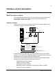
Setting up communication through a FPBA-01 fieldbus adapter module
Before configuring the drive for fieldbus control, the adapter module must be
mechanically and electrically installed according to the instructions given in the
FPBA-01 user’s manual.
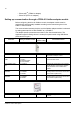
The communication between the drive and the fieldbus adapter module is activated
by setting parameter 50.01 FBA ENABLE to (1) ENABLE.
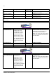
The adapter-specific parameters must also be set. See the table below. The
Application-specific setting column is a setup for speed control using ABB Drives
profile and PPO type 5.
Parameter Setting for fieldbus control
Application-
specific setting
Function/Information
COMMUNICATION INITIALISATION AND SUPERVISION
50.01 FBA ENABLE (1) ENABLE (1) ENABLE Initialises communication between drive
and fieldbus adapter module.
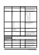
50.02 COMM LOSS
FUNC
(0) NO
(1) FAULT
(2) SPD REF SAFE
(3) LAST SPEED
(1) FAULT Selects how the drive reacts in a fieldbus
communication break.
50.03 COMM LOSS T
OUT
0.3…6553.5 s 0.3 Defines the time between communication
break detection and the action selected
with parameter 50.02 COMM LOSS
FUNC.
50.04 FBA REF1
MODESEL
(0) RAW DATA
(1) TORQUE
(2) SPEED
(2) SPEED Selects the fieldbus reference FBA REF1
scaling and the actual value, which is sent
to the fieldbus (FBA ACT1).
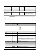
50.05 FBA REF2
MODESEL
(0) RAW DATA
(1) TORQUE
(2) SPEED
(1) TORQUE Selects the fieldbus reference FBA REF2
scaling and the actual value, which is sent
to the fieldbus (FBA ACT2).
FPBA-01 ADAPTER MODULE CONFIGURATION
51.01 FBA TYPE Profibus DP Profibus DP Displays the type of the fieldbus adapter
module.