
Hardware manual


Fieldbus control description
16
51.31 D2FBA COMM
STA
– Displays the status of the fieldbus adapter
module communication.
51.32 FBA COMM SW
VER
– Displays the common program revision of
the adapter module.
51.33 FBA APPL SW
VER
– Displays the application program revision
of the adapter module.
Note: In the User’s Manual of the fieldbus adapter module, the parameter group number is 1 or A for parameters
51.01…51.26.
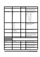
TRANSMITTED DATA SELECTION FROM DRIVE TO PLC
52.01 FBA DATA IN1 ...
52.12 FBA DATA IN12
0 Not selected
4 Status word (16-bit)
5 Actual value 1 (16-bit)
6 Actual value 2 (16-bit)
14 Status word (32-bit)
15 Actual value 1 (32-bit)
16 Actual value 2 (32-bit)
101…9999 Drive pameters
(For example value 101
points to drive parameter
1.01)
Defines the data transmitted from drive to
fieldbus controller and further to the PLC.
Parameters are set according to the
virtual address area of the drive.
Note: If the length of the selected data is
32 bits, two parameters are reserved for
the transmission.
52.01 FBA DATA IN1 4 Status word (16-bit)
52.02 FBA DATA IN 2 5 Actual value 1 (16-bit)
52.03 FBA DATA IN 3 6 Actual value 2 (16-bit)
TRANSMITTED DATA SELECTION FROM PLC TO DRIVE
53.01 FBA DATA OUT 1
… 53.12 FBA DATA OUT
12
0 Not selected
1 Control word
2 Reference 1 (16-bit)
3 Reference 2 (16-bit)
11 Control word (32-bit)
12 Reference 1 (32-bit)
13 Reference 2 (32-bit)
1001…9999 Drive pameters
(For example value 1001
points to drive parameter
10.01)
Defines the data transmitted from fieldbus
controller to drive.
Note: If the length of the selected data is
32 bits, two parameters are reserved for
the transmission.
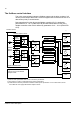
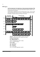
Parameter Setting for fieldbus control
Application-
specific setting
Function/Information