
Hardware manual


Communication profiles
27
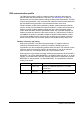
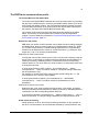
The Control Word for the PROFIdrive communication profile
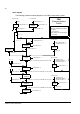
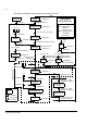
The upper case boldface text refers to the states shown on page 30.
Bit Name Value Proceed to STATE/Description
Speed control mode
0 ON 1 Proceed to READY TO OPERATE.
OFF1 0 Emergency OFF, stop by the selected deceleration ramp. Proceed to OFF1
ACTIVE; proceed further to READY TO SWITCH ON unless other interlocks
(OFF2, OFF3) are active.
1 OFF2 1 Continue operation (OFF2 inactive).
0 Emergency OFF, coast to stop.
Proceed to OFF2 ACTIVE; proceed further to SWITCH-ON INHIBIT.
2 OFF3 1 Continue operation (OFF3 inactive).
0 Emergency stop, stop according to fastest possible deceleration mode. Proceed
to OFF3 ACTIVE; proceed further to SWITCH-ON INHIBIT.
Warning! Ensure that the motor and driven machine can be stopped using this
stop mode.
3 OPERATION_ENA
BLE
1 Proceed to ENABLE OPERATION.
0 Inhibit operation. Proceed to OPERATION INHIBIT.
4 ENABLE_
RAMP_
GENERATOR
or
TRAVERSING
_TASK
1 Normal operation.
Proceed to RAMP FUNCTION GENERATOR: ENABLE OUTPUT.
0 Stop according to selected stop type.
5 1 Normal operation.
Proceed to RAMP FUNCTION GENERATOR: ENABLE ACCELERATOR.
0 Halt ramping (Ramp Function Generator output held).
6 1 Normal operation. Proceed to OPERATING.
Note: This bit is effective only if the fieldbus interface is set as the source for this
signal by drive parameters.
0 Force Ramp Function Generator input to zero.
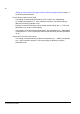
7 RESET 0 ⇒ 1 Fault reset if an active fault exists. Proceed to SWITCH-ON INHIBIT.
Note: This bit is effective only if the fieldbus interface is set as the source for this
signal by drive parameters.
0 (Continue normal operation)
8 JOGGING_1 Jogging 1. (Not supported by all drive types)
9 JOGGING_2 Jogging 2. (Not supported by all drive types)
10 REMOTE_
CMD
1 Fieldbus control enabled.
0 Control Word <> 0 or Reference <> 0: Retain last Control Word and Reference.
Control Word = 0 and Reference = 0: Fieldbus control enabled.