
Hardware manual

Installation and parameter setup for communication profiles
37
Installation and parameter setup for
communication profiles
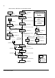
Overview
This chapter presents the steps to take during the start-up of the FPBA-01
PROFIBUS DP Adapter Module and the ACS850 drive. This chapter presents
examples for different applications such as speed and torque control, sending
reference over fieldbus and scaling. For more detailed information, see PROFIBUS
DP Adapter Module FPBA-01 User’s Manual (3AFE68573271 [English]), ACS850
Standard Control Program Firmware Manual (3AUA0000045497 [English]) and
appropriate hardware manual, such as ACS850-04 Drive Modules (1.1 to 45 kW)
Hardware Manual (3AUA0000045496 [English]).
WARNING! Follow the safety instructions given in this manual and in the hardware
manual of the drive.
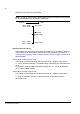
Mechanical and electrical installation
1 Insert the FPBA-01 into slot 3 in the drive.
2 Fasten the screw.
3 Plug and fasten the Profibus DP connector to the module.
4 Connect the other end of the profibus cable to a profibus master (PLC).
5 Power up the drive
6 Power up the profibus master (PLC).
For more detailed information see appropriate User/Hardware manual.
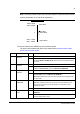
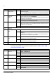
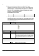
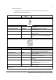
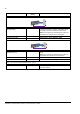
Parameter setup examples
This section gives the recommended drive parameter settings for different
communication profiles. For more information on the communicaton profiles used in
the communication between the PROFIBUS network, the FPBA-01 module and the
drive, such as the contents of the Control Word and Status Word and the state
machines of the profiles, refer to chapters Fieldbus control description and
Communication profiles.
Note: An ID run must be performed before commissioning. For more information see
ACS850 Standard Control Program Firmware Manual (3AUA0000045497 [English]).