
Hardware manual


Installation and parameter setup for communication profiles
49
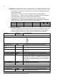
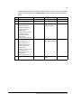
The Control Word is used for sending commands from a master (PLC) to a slave unit
(Drive). The start sequence for speed control in this example is given in the table
below.
Step Instruction Control Word (Hex) Operation Status Word
1 Power up 0x0000 Fault active 0x1338
2 Reset fault (bit 7)
Remote command (bit 10)
0x0480 Reset fault 0x0380
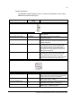
3 OFF2 inactive (bit 1)
OFF3 inactive (bit 2)
Operation enabled (bit 3)
Enable ramp function
generator (bit 4)
Enable ramp function (bit 5)
Force ramp function
generator input to zero
inactive (bit 6)
Remote command (bit 10)
0x047e OFF1 active
Ready to operate
0x1331
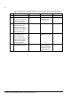
4 OFF1 inactive (bit 0)
OFF2 inactive (bit 1)
OFF3 inactive (bit 2)
Operation enable (bit 3)
Enable ramp function
generator (bit 4)
Enable ramp function (bit 5)
Force ramp function
generator input to zero
inactive (bit 6)
Remote command (bit 10)
0x047f Operating
Drive starts to modulate
0x1337
5 Set speed reference value to
200
0x047f Motor runs at reference
speed
0x1337